123
21 INSTALLATION EXAMPLES
The following schematics present several examples of heating installations:
All schematics are purely functional.
Safety components, bypass, control devices and so on must be added conform all
applicable standards and regulations.
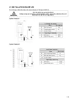
System Example 1
Low Voltage Connections
Name
Wire terminal
RT
Room thermostat
12-13
FS
Flow temperature sensor
3-4
LLH
Low loss header
High Voltage Connections
P1
boiler pump
4-PE-5
P3
system heating pump
6-PE-7
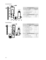
System Example 2
Low Voltage Connections
Name
Wire terminal
OS
outdoor temperature sensor
1-2
FS
Flow temperature sensor
3-4
LLH Low loss header
High Voltage Connections
P1
boiler pump
4-PE-5
P3
system heating pump
6-PE-7
P1
HEATING
ZONE
BOILER
RT
P3
P3
P1
HEATING
ZONE
BOILER
OS
WARNING
LLH
FS
FS
LLH
Summary of Contents for S-CBX 105
Page 2: ......
Page 40: ...40 9 10 Flue Terminal Positioning ...
Page 42: ...42 9 11 1 FIGURE 12 LINE G ...
Page 55: ...55 11 5 Ladder Logic Diagram ...
Page 56: ...56 11 6 Electrical schematics ...
Page 57: ...57 ...
Page 137: ......

