125
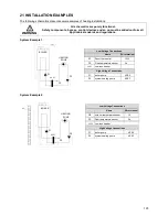
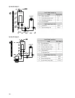
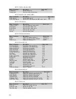
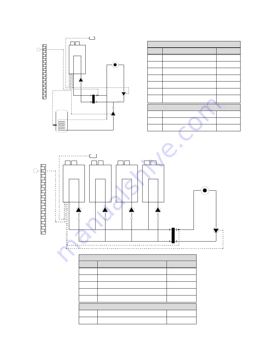
System Example 5
Low Voltage Connections
Name
Wire terminal
RT
Room thermostat
12-13
FS
flow temperature sensor
3-4
OS
outdoor temperature sensor
1-2
ST
Tank thermostat or sensor
5-6
LLH low loss header
T
DHW indirect Tank
SNV non-return valve
(low resistance type)
High Voltage Connections
P1
boiler pump
4-PE-5
P2
HWS primary pump
2-3-PE
P3
System heating pump
6-PE-7
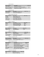
System Example 6
Low Voltage Connections
Name
Wire terminal
RT
Room thermostat
12-13
OS
outdoor temperature sensor
1-2
FS
flow temperature sensor
3-4
SNV
non-return valve (low resistance type)
LLH
low loss header
High Voltage Connections
P1
boiler pump
4-PE-5
P3
System heating pump
6-PE-7
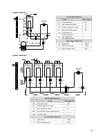
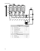
LLH
FS
RT
P3
P1
HEATING
ZONE
BOILER
OS
ST
P2
SNV
SNV
T
P1
P1
P1
P1
P3
LLH
FS
OS
RT
SNV
SNV
SNV
SNV
BOILER 1
managing
HEATING
ZONE
BOILER 2
depending 1
BOILER 3
depending 2
BOILER 4
depending 3
Summary of Contents for S-CBX 105
Page 2: ......
Page 40: ...40 9 10 Flue Terminal Positioning ...
Page 42: ...42 9 11 1 FIGURE 12 LINE G ...
Page 55: ...55 11 5 Ladder Logic Diagram ...
Page 56: ...56 11 6 Electrical schematics ...
Page 57: ...57 ...
Page 137: ......

