4
9.5.1
Air contamination ........................................................................................................ 32
9.6
P
ROPER VENT INSTALLATION AND TYPE OF GAS VENT OR VENT CONNECTOR
. .............................. 33
9.7
B
OILER CATEGORIES
-
TYPES OF FLUE GAS SYSTEMS
. ................................................................ 34
9.8
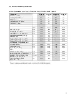
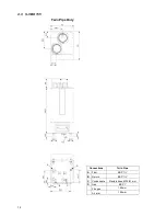
C63
CERTIFIED
........................................................................................................................ 38
9.9
P
IPE HEIGHTS AND MUTUAL DISTANCES ON A FLAT ROOF
............................................................ 39
9.10
F
LUE
T
ERMINAL
P
OSITIONING
.................................................................................................. 40
9.11
H
ORIZONTAL
F
LUE
R
UN
R
ISK
A
SSESSMENT
.............................................................................. 41
9.11.1
Figure 12 – line G ....................................................................................................... 42
9.12
F
LUE GAS AND AIR SUPPLY RESISTANCE TABLE
.......................................................................... 43
9.13
T
YPICAL EXAMPLES
.................................................................................................................. 45
9.13.1
Example A: Twin pipe system with separate pipes for flue outlet and air supply ....... 45
9.13.2
Example B: Twin pipe system with concentric roof terminal ....................................... 46
9.13.3
Example C: Single flue gas outlet. Air supply from boiler room.................................. 48
9.13.4
Example D: Concentric flue gas/air supply pipe (roof-mounted) ................................ 49
9.13.5
Example E: Concentric system Wall outlet C13 (wall-mounted) ................................ 49
10
CASCADING ....................................................................................................................................... 51
10.1
A
PPLIANCE
.............................................................................................................................. 51
11
ELECTRICAL INSTALLATION .......................................................................................................... 52
11.1
G
ENERAL
................................................................................................................................ 52
11.2
E
LECTRICAL CONNECTIONS
...................................................................................................... 52
11.3
E
XPLANATION OF THE LOW VOLTAGE CONNECTIONS
. ................................................................. 53
11.4
E
XPLANATION OF THE HIGH VOLTAGE CONNECTIONS
.................................................................. 54
11.5
L
ADDER
/L
OGIC
D
IAGRAM
......................................................................................................... 55
11.6
E
LECTRICAL SCHEMATICS
........................................................................................................ 56
11.7
S
ENSOR AVAILABILITY
.............................................................................................................. 58
11.8
NTC
SENSOR CURVE
............................................................................................................... 58
11.9
P
ROGRAMMABLE IN
-
AND OUTPUTS
........................................................................................... 59
12
BURNER CONTROLLER AND DISPLAY. ........................................................................................ 60
12.1
D
ISPLAY AND BUTTONS
............................................................................................................ 60
12.1.1
Display icons ............................................................................................................... 61
12.2
S
CREENS AND SETTINGS
. ......................................................................................................... 61
12.2.1
Set Actual setpoint/DHW setpoint directly via the Status overview ............................ 61
12.2.2
Entering the menu ....................................................................................................... 62
12.2.3
Protected menu items ................................................................................................. 63
12.2.4
De-aeration Sequence ................................................................................................ 63
12.2.5
Language settings ....................................................................................................... 63
12.3
B
OILER HISTORY
...................................................................................................................... 64
12.4
E
RROR LOGGING
. .................................................................................................................... 64
12.5
G
ENERAL
................................................................................................................................ 65
12.5.1
Pump start exercise every 24 hours ........................................................................... 65
12.5.2
Frost protection ........................................................................................................... 65
12.5.3
Appliance selection ..................................................................................................... 66
12.6
I
GNITION CYCLE
....................................................................................................................... 66
12.6.1
Flame detection .......................................................................................................... 67
12.6.2
Flame recovery ........................................................................................................... 67
12.7
C
ONTROL FUNCTIONS
.............................................................................................................. 68
12.7.1
Room thermostat only; CH mode 0 (Default setting) .................................................. 68
12.7.2
CH with an outdoor temperature reset and THERMOSTAT; CH mode 1 .................. 69
12.7.3
CH with constant circulation system outdoor RESET; CH mode 2 ............................ 71
12.7.4
CH with constant circulation and permanent heat demand; CH mode 3 .................... 71
12.7.5
Central Heating with analogue input control of setpoint; CH mode 4 ......................... 72
12.7.6
CH with analogue input control of power output; CH mode 5 ..................................... 73
12.8
D
EMAND FOR
D
OMESTIC
H
OT
W
ATER
...................................................................................... 74
12.8.1
No Domestic Hot Water; DHW mode 0 ...................................................................... 74
12.8.2
DHW Storage with sensor; DHW mode 1 ................................................................... 74
12.8.3
DHW Storage with thermostat; DHW mode 2............................................................. 75
12.8.4
Instantaneous water heating with plated heat exchanger; DHW mode 3 ................... 75
12.8.5
Anti-legionella protection............................................................................................. 76
12.8.6
Display menu structure summary. .............................................................................. 77
13
TEMPERATURE PROTECTION ........................................................................................................ 84
14
ERROR INFORMATION. .................................................................................................................... 85
Summary of Contents for S-CBX 105
Page 2: ......
Page 40: ...40 9 10 Flue Terminal Positioning ...
Page 42: ...42 9 11 1 FIGURE 12 LINE G ...
Page 55: ...55 11 5 Ladder Logic Diagram ...
Page 56: ...56 11 6 Electrical schematics ...
Page 57: ...57 ...
Page 137: ......


