44
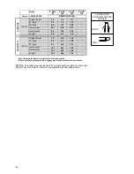
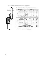
Boiler
S-CBX
85
S-CBX
105
S-CBX
125
S-CBX
155
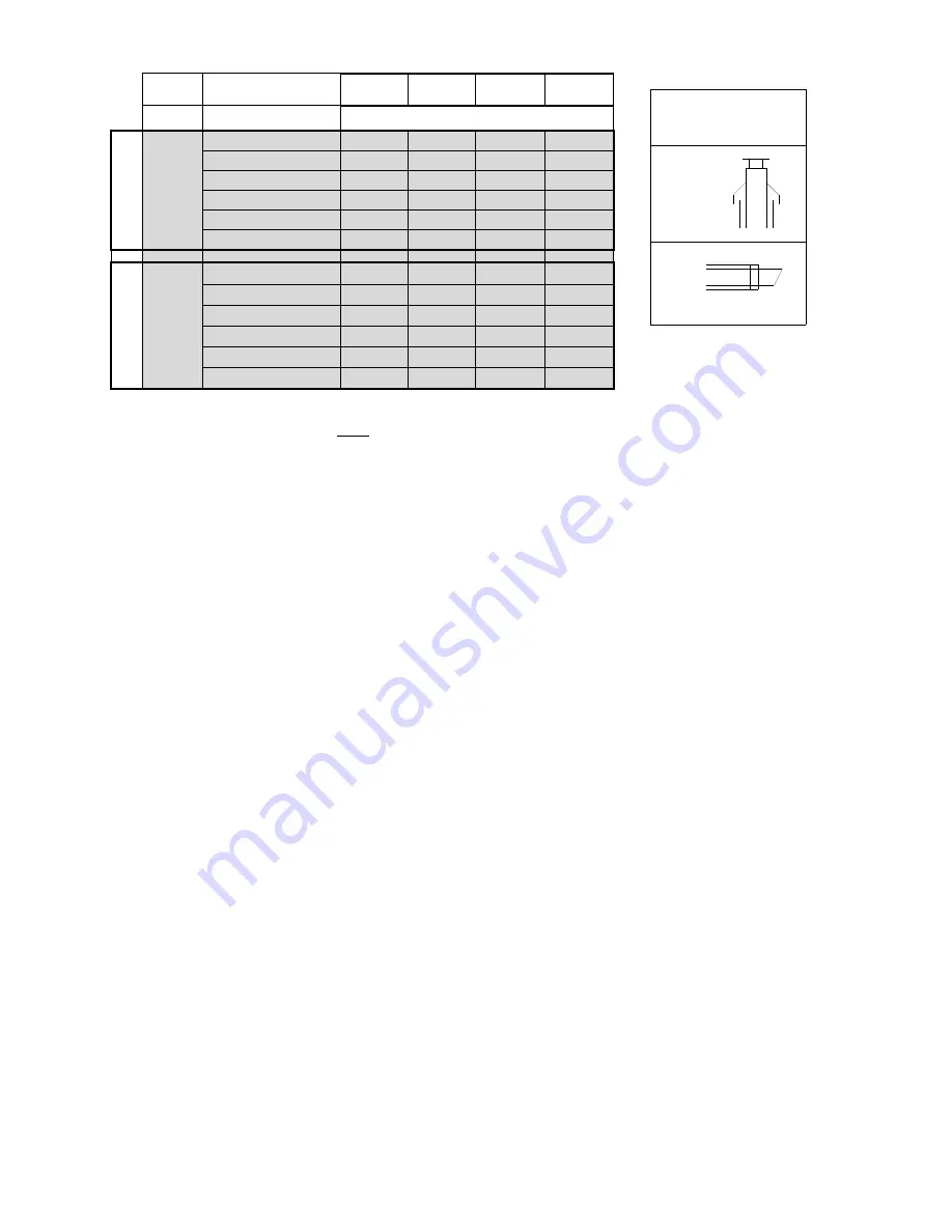
Ø mm CONCENTRIC
RESISTANCE [Pa]
FL
UE G
AS
100/150
straight tube/m
2.4
3.4
5.2
-
45° bend
5.3
7.5
11.3
-
90° bend
8.5
12.1
18.3
-
roof terminal
26.1
37.0
55.7
-
wall terminal
9.0
12.8
19.2
-
adaptor
0.4
0.5
0.8
-
AIR SUPPLY
100/150
straight tube/m
7.4
10.5
15.8
-
45° bend
6.5
9.2
13.8
-
90° bend
9.4
13.4
20.1
-
roof terminal
34.7
49.3
74.2
-
wall terminal
34.7
49.3
74.2
-
adaptor
32.8
46.5
70.0
-
* Never reduce pipe diameters relative to boiler connections
Values printed in grey applicable for larger pipe diameters than boiler connection
NOTICE: This table may only be used for a single flue/air system for one boiler.
Do NOT use this table for common flue systems with cascaded boilers.
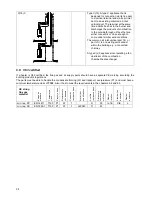
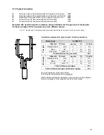
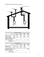
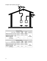
CONCENTRIC
FLUE GAS OUTLET
AIR INLET
ROOF
WALL
Summary of Contents for S-CBX 105
Page 2: ......
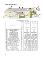
Page 40: ...40 9 10 Flue Terminal Positioning ...
Page 42: ...42 9 11 1 FIGURE 12 LINE G ...
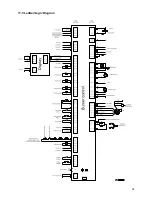
Page 55: ...55 11 5 Ladder Logic Diagram ...
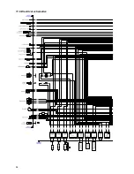
Page 56: ...56 11 6 Electrical schematics ...
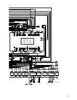
Page 57: ...57 ...
Page 137: ......

