49
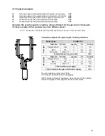
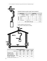
9.13.4 E
XAMPLE
D:
C
ONCENTRIC FLUE GAS
/
AIR SUPPLY PIPE
(
ROOF
-
MOUNTED
)
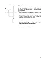
Calculation example with given lengths: checking resistance
Boiler type:
S-CBX 85
FL
U
E
G
A
S
Diameter: 100/150 mm.
quantity
Pa
Pa total
Straight tube m
total
11
2.4
26.4
Bend
90°
3
8.5
25.5
Bend
45°
2
5.3
10.6
Concentric terminal
roof
1
26.1
26.1
resistance flue gas:
88.6
A
IR
S
U
PP
LY
Diameter: 100/150 mm.
quantity
Pa
Pa total
Straight tube m
total
11
7.4
81.4
Bend
90°
3
9.4
28.2
Bend
45°
2
6.5
13.0
Concentric terminal
roof
1
34.7
34.7
resistance air supply:
157.3
Total resistance flue gas and air supply:
245.9
The total resistance is more than 200 Pa.
This flue gas / air supply system is NOT functional.
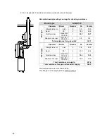
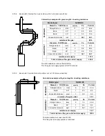
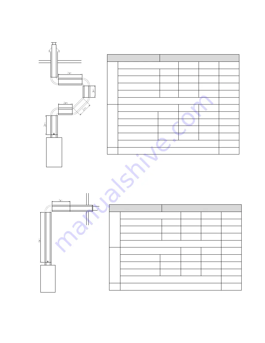
9.13.5 E
XAMPLE
E:
C
ONCENTRIC SYSTEM
W
ALL OUTLET
C13
(
WALL
-
MOUNTED
)
Calculation example with given lengths: checking resistance
Boiler type:
S-CBX 85
FL
U
E
G
A
S
Diameter: 100/150 mm.
quantity
Pa
Pa total
Straight tube m
total
9
2.4
21.6
Bend
90°
1
8.5
8.5
Concentric terminal
wall
1
9.0
9.0
resistance flue gas outlet:
39.1
A
IR
S
U
PP
LY
Diameter: 100/150 mm.
quantity
Pa
Pa total
Straight tube m
total
9
7.4
66.6
Bend
90°
1
9.4
9.4
Concentric terminal
wall
1
34.7
34.7
resistance air supply:
34.7
Total resistance flue gas outlet and air supply:
149.8
The total resistance is less than 200 Pa.
This flue gas / air supply system is functional.
Summary of Contents for S-CBX 105
Page 2: ......
Page 40: ...40 9 10 Flue Terminal Positioning ...
Page 42: ...42 9 11 1 FIGURE 12 LINE G ...
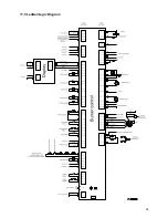
Page 55: ...55 11 5 Ladder Logic Diagram ...
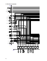
Page 56: ...56 11 6 Electrical schematics ...
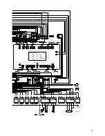
Page 57: ...57 ...
Page 137: ......

