54
11.4 Explanation of the high voltage connections.
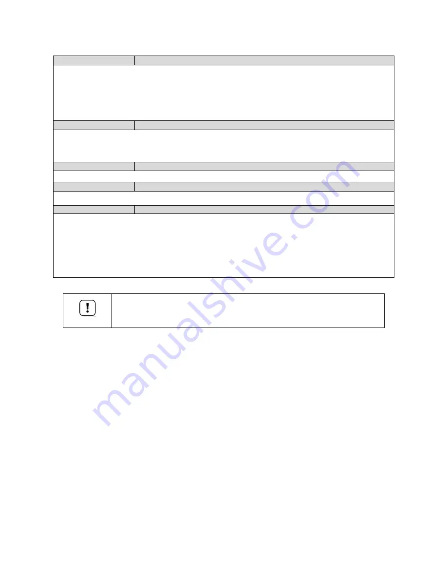
1-2-3-PE
DIVERTER VALVE DHW indirect tank
If an indirect domestic hot water tank is installed, a 3-way valve or a pump (P2) can be used to divert hot water
to the heating coil of the tank. This 3-way valve will open, or pump will power on, when the indirect tank has a
heat demand.
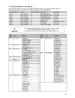
PARAMETER: boiler parameter 128, see: § 11.9 "programmable in- and outputs"
1 = L1 wire (heating position); 2 = Neutral wire; 3 = L2 (hot water position); PE = Ground.
The inrush current of the 3-way valve or pump may not exceed 8 Amps, see chapter 8.4 for detailed electrical
specifications.
4-PE-5
SYSTEM PUMP
Connections for the power supply of a central heating system pump (P3, see chapter 8.4 for detailed electrical
specifications).
4 = Phase wire; 5 = Neutral wire; PE = Ground
PARAMETER: Boiler parameter 125, see chapter 11.9 "programmable in- and outputs"
6-PE-7
BOILER PUMP
Connections for the power supply of a boiler pump. (P1, see chapter 8.4 for detailed electrical specifications).
8-9-PE-PE
MAINS SUPPLY
The power supply connection of the unit. 8 = Line voltage wire; 9 = Neutral wire, PE = Ground wire
10-11
ALARM RELAY
A semiconductor alarm output. This is a triac output with an active voltage of 230 VAC, it can only handle
resistive loads between 5 and 50 Watt. E.g. an incandescent bulb of 10-50 Watt can be added to this.
This alarm will be activated 60 seconds after an error has occurred.
There are a few exceptions:
- Alarm output will not be activated for a service warning;
- Alarm output will not be activated for warning 202 (Appliance selection).
10 = Phase wire; 11 = Neutral wire
PARAMETER: boiler parameter 127, see: § 11.9 "programmable in- and outputs"
To all outputs following applies: maximum current 1.5 A each output.
Total output of all currents combined maximum 3.5 A.
The inrush current of the 3-way valve and/or pumps is maximum 8 A.
NOTICE
Summary of Contents for S-CBX 105
Page 2: ......
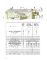
Page 40: ...40 9 10 Flue Terminal Positioning ...
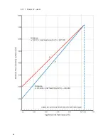
Page 42: ...42 9 11 1 FIGURE 12 LINE G ...
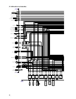
Page 55: ...55 11 5 Ladder Logic Diagram ...
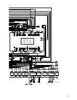
Page 56: ...56 11 6 Electrical schematics ...
Page 57: ...57 ...
Page 137: ......

