61
12.1.1 D
ISPLAY ICONS
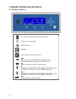
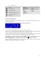
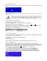
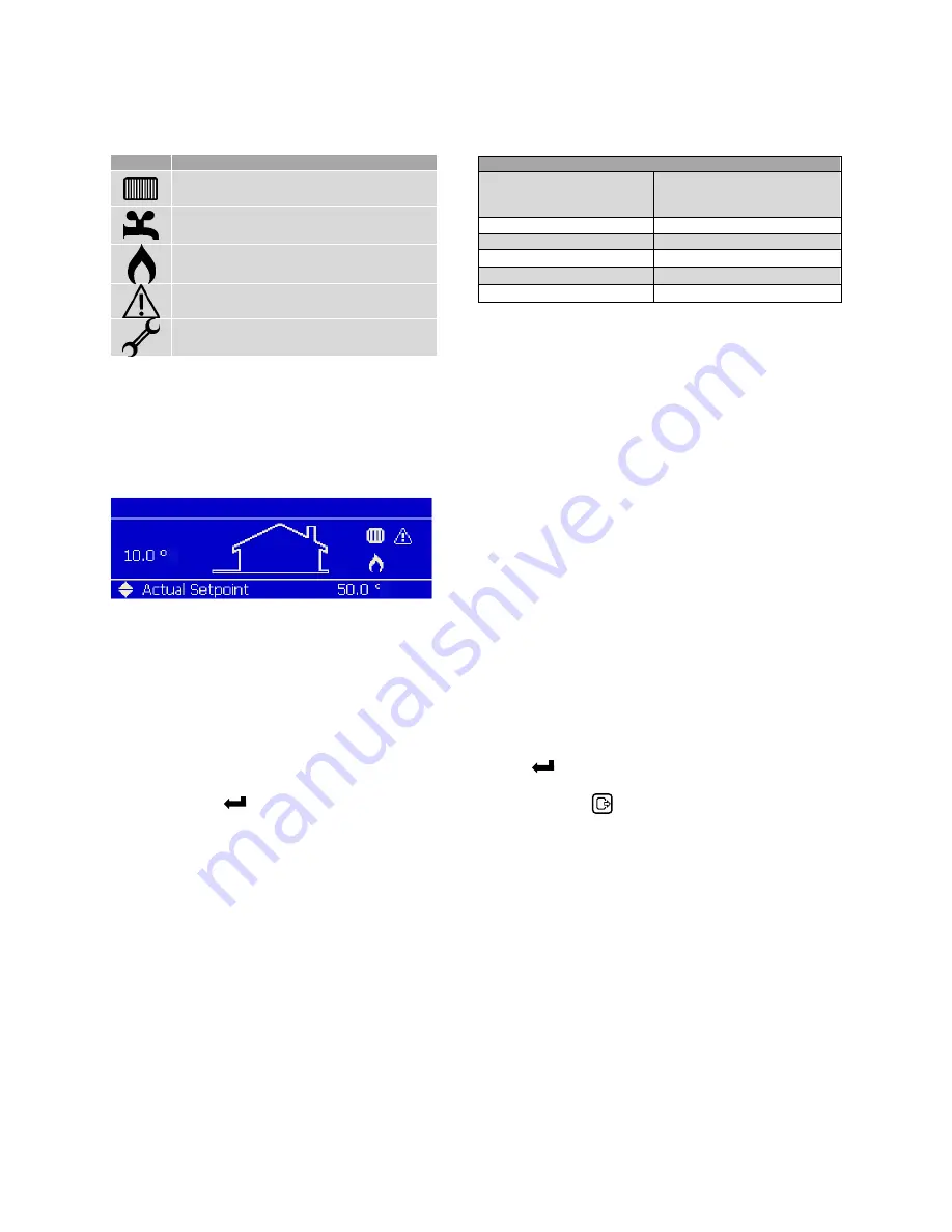
The following table gives a short description of the icons that can be visible on the main screen during operating:
12.2 Screens and settings.
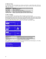
This screen is active during power up and will remain active until communication with the Main Control (the AL-
BUS) has been established.
After communication has been established the following
Status overview
appears:
12.2.1 S
ET
A
CTUAL SETPOINT
/DHW
SETPOINT DIRECTLY VIA THE
S
TATUS OVERVIEW
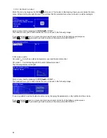
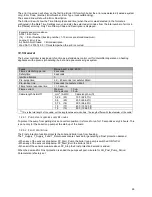
When CH is active, you can adjust the Actual setpoint directly on the bottom of the Status overview. When DHW
is active, you can adjust the DHW setpoint directly on the bottom of the Status overview.
This means that when CH is active, you cannot set the DHW setpoint directly via the Status overview. When DHW
is active, you also cannot set the Actual setpoint (CH setpoint) directly via the Status overview.
Press UP/DOWN ↑↓ to select the mode, then press CONFIRM or RIGHT → to confirm the mode and the
Actual/DHW setpoint becomes directly settable. Use UP ↑ or DOWN ↓ to increase/decrease the setpoint.
Press CONFIRM or RIGHT → to confirm your alteration or press ESC or LEFT ← to cancel.
A setpoint is only visible on the display when no error or alert is active. In case of an active error or alert, the bottom
right part of the display is used to display the error or alert text.
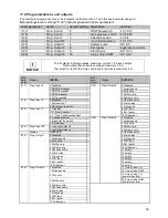
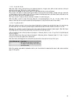
Boiler Status
CH control state
(Central Heating controller
state)
RT_Input
(Room thermostat open of
closed)
0 = Idle
0=Open
1 = Request
1=Closed
2 = Demand
3 = Post circulation
4 = Off
Icon
Description
Central Heating demand
Domestic Hot Water demand
Indicates that the appliance burner is ON
Cascade Emergency Mode active
Error notification
C
C
Summary of Contents for S-CBX 105
Page 2: ......
Page 40: ...40 9 10 Flue Terminal Positioning ...
Page 42: ...42 9 11 1 FIGURE 12 LINE G ...
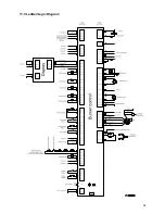
Page 55: ...55 11 5 Ladder Logic Diagram ...
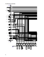
Page 56: ...56 11 6 Electrical schematics ...
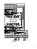
Page 57: ...57 ...
Page 137: ......

