background image


65 

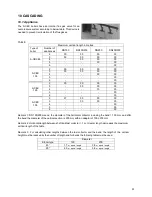
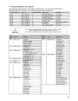
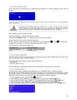
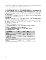
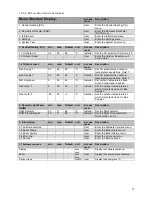
The error log screen will show on the first line: Boiler ID for which boiler the error was detected (cascade system 

only), Error Code, (internal) Error Number, Error Type (Lockout/Blocking). 

The second line will show the Error Description. 

The bottom line will show the Time Stamp (date and time) when the error was detected (in the format as 

configured in the Date Time Settings menu), and also the selected error index from the total number of errors in 

the (filtered) error log. Only Time Stamp, Code and Description is displayed. 


Example see picture above. 

A014 = Error code. 

(14)   = Error Number (tracking number, 1-15 errors are stored maximum). 

Lockout = Error type. 

Air Switch Not Closed   = Error description. 

Wed 04-11-2018 14:50 = Time stamp when the error occurred. 


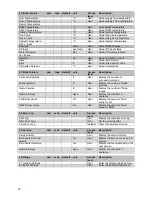
12.5  General 

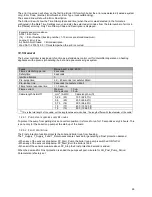
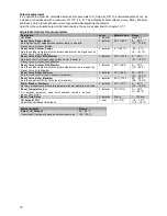
The burner controller is designed to function as a standalone control unit for intermittent operation on heating 

appliances with a premix (modulating) burner and a pneumatic air-gas system. 
 

Fuses 

Mains input 1 x 5AT, 230V 

Flame establishing period 

2 seconds 

Safety time 

5 seconds 

Ignition attempts 

Pre-purge time 

≥ 2…60 seconds (not safety critical) 

Pre-ignition time 

2 seconds (not safety critical) 

Flame failure response time 

< 1.0 second 

Flame-current 

Minimum   

1.0 μA  

Start-detection  1.5 μA 

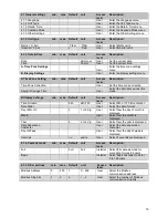
Cable length AL-BUS

1


  mm

2

   (AWG)          Cable length m (ft) 

   0.25     (23)              100  (328.1 ft) 

   0.5       (20)              200  (656.2 ft) 

   0.75     (18)              300  (984.3 ft) 

   1.0       (17)              400  (1312.3 ft) 

   1.5       (15)              600  (1968.5 ft) 

1) This is the total length of the cable, not the length between two boilers. The length differs with the diameter of the cable.


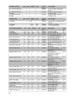
12.5.1   P

UMP START EXERCISE EVERY 

24

 HOURS


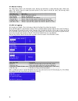
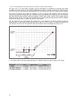
To protect the pump from getting stuck at a certain position it is forced to run for 10 seconds every 24 hours. This 

is done only for the boiler loop pump at the start-up of the board. 

12.5.2   F

ROST PROTECTION


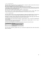
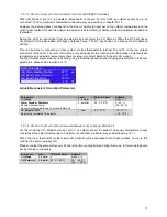
The Frost protection function protects the boiler and boiler loop from freezing. 

The T_Supply, T_Supply_2 and T_Return sensors are checked for generating a Frost protection demand. 


• When any of the sensors drop below FP_Start_Pump the boiler loop pump is switched ON for CH. 

• When any of the sensors drop below FP_Start_Burn the boiler is fired. 

• When all of the sensors measure above FP_Stop the Frost protection demand is ended. 


When the demand for Frost protection is ended the pumps will post-circulate for CH_Post_Pump_Period. 

Parameters are factory set 


Summary of Contents for S-CBX 105

Page 1: ...s 85 105 125 155 Wall Hung High Efficiency Condensing Boiler Installation Operating Maintenance Manual Please read and understand before commencing installation and leave the manual with the customer for future reference 2019 02 01 v2 ...

Page 2: ......

Page 3: ...LITY 20 7 9 FROST PROTECTION 20 7 10 INSTALLING A STRAINER AND OR DIRT SEPARATOR 21 7 11 WATER QUALITY 21 7 12 USE OF GLYCOL 22 7 13 CHEMICAL WATER TREATMENT 22 7 14 FLUSH THE SYSTEM WITH FRESH WATER 23 7 15 PLASTIC PIPING IN THE HEATING SYSTEM 23 7 16 DE AIR SEQUENCE 24 7 17 AUTOMATIC FEED VALVE SYSTEMS 24 7 18 WATER PRESSURE 25 7 19 INSTALLATION EXAMPLES 25 7 19 1 Example of a normal single boil...

Page 4: ... AND DISPLAY 60 12 1 DISPLAY AND BUTTONS 60 12 1 1 Display icons 61 12 2 SCREENS AND SETTINGS 61 12 2 1 Set Actual setpoint DHW setpoint directly via the Status overview 61 12 2 2 Entering the menu 62 12 2 3 Protected menu items 63 12 2 4 De aeration Sequence 63 12 2 5 Language settings 63 12 3 BOILER HISTORY 64 12 4 ERROR LOGGING 64 12 5 GENERAL 65 12 5 1 Pump start exercise every 24 hours 65 12 ...

Page 5: ...7 3 THIRD CHECK THE WATER FLOW 103 17 4 MOUNTING CONDENSATE TRAP 104 17 5 CHECKING GAS PRESSURE 104 17 6 FIRING FOR THE FIRST TIME 104 18 ADJUSTING AND SETTING THE BOILER 105 18 1 INTRODUCTION 105 18 1 1 Combustion table 105 18 1 2 Setting screws venturi and gas valves drawings 106 18 2 ADJUSTMENT PROCEDURES 107 18 3 VENTURI REPLACEMENT ADJUSTMENT 107 18 4 CONVERSION FROM NATURAL GAS TO PROPANE 10...

Page 6: ...3 22 12 10 General Settings 133 22 12 11 Language 133 22 12 12 Unit Type 133 22 12 13 Date Time 133 22 12 14 Time zone settings 133 22 12 15 Display settings 133 22 12 16 Cascade mode 133 22 12 17 Other Settings 134 22 12 18 Boiler settings 134 22 13 BOILER HISTORY 134 22 14 ERROR LOGGING 134 22 15 SERVICE REMINDER 135 22 15 1 Service overdue logging 135 22 15 2 Service reminder implementations 13...

Page 7: ...pliance and to replace any part of the control system and any gas control which has been under water What to do if you smell gas Do not use any electrical equipment Do not press any switches Close the gas supply Ventilate the room open the windows and or outdoor water heater room doors Immediately warn the installer The manufacturer supplier is not liable for any damage caused by inaccurately foll...

Page 8: ...n from each boiler Weather compensation control Calorifier control Connections for On Off thermostat 0 10 VDC remote flow temperature set point control 0 10 VDC remote burner input control Outdoor temperature sensor External calorifier pump or diverter valve Boiler pump PWM control for external boiler pump System pump External flow switch or external safety device Modbus External system sensor DHW...

Page 9: ...54 4 Nominal input net G31 kW 16 0 80 5 19 0 95 2 24 1 120 8 39 3 142 2 Nominal output 80 60 C G20 kW 14 9 79 1 18 0 94 2 22 9 115 7 33 9 140 9 Nominal output 50 30 C G20 kW 16 0 85 1 19 5 101 8 24 7 124 7 36 4 151 0 Nominal output 37 30 C G20 kW 16 6 88 4 20 2 105 5 25 6 129 4 38 0 157 8 Nominal output 80 60 C G25 3 kW 15 2 77 0 18 1 92 3 23 1 113 4 34 3 137 9 Nominal output 50 30 C G25 3 kW 16 4...

Page 10: ... 20 C C 60 90 Mass flow flue gas min max g s 8 0 42 10 51 12 62 15 76 Available pressure for the flue system 4 Pa 200 INSTALLATION Resistance boiler T 20 K m W C 4 0 3 4 3 8 3 6 T 25 K m W C 2 8 2 3 2 5 2 4 Pressure boiler min max bar 1 0 6 0 Max flow temperature C 90 ELECTRIC Maximum power consumption 5 W 190 280 280 280 Power supply V Hz 230 50 Protection class IPX4D NOTES 3 CO2 of the unit meas...

Page 11: ...8 8 46 5 Seasonal space heating energy efficiency ɳs 92 4 92 6 92 7 92 9 Energy efficiency ɳ4 at 60 80 C 87 2 87 2 87 3 87 3 Energy efficiency ɳ1 at 30 37 C 97 4 97 6 97 7 97 8 Auxiliary electricity consumption At full load elmax kW 0 183 0 271 0 280 0 278 At part load elmin kW 0 024 0 023 0 027 0 031 In standby mode Psb kW 0 007 0 007 0 007 0 007 Other Standby heat loss Pstby kW 0 066 0 070 0 075...

Page 12: ...S CONNECTIONS 4 1 S CBX 85 105 Twin Pipe Concentric Coaxial Connections Twin Pipe Concentric A Flow BSP 1 B Return BSP 1 C Condensate Flexible hose Ø 25 21 mm D Gas BSP Flue gas 100 mm 100 150 mm Air inlet 100 mm 100 150 mm ...

Page 13: ... D 4 2 S CBX 125 Twin Pipe Concentric Coaxial Connections Twin Pipe Concentric A Flow BSP 1 B Return BSP 1 C Condensate Flexible hose Ø 25 21 mm D Gas BSP Flue gas 100 mm 100 150 mm Air inlet 100 mm 100 150 mm ...

Page 14: ...14 A B C D 4 3 S CBX 155 Twin Pipe Only Connections Twin Pipe A Flow BSP 1 B Return BSP 1 C Condensate Flexible hose Ø 25 21 mm D Gas BSP 1 Flue gas 150 mm Air inlet 150 mm ...

Page 15: ...culating Pump for S CBX 155 S022 500 013 WIFI module IP module S022 500 006 External ignition transformer S022 500 016 Propane orifice S CBX 85 105 S022 500 001 Propane orifice S CBX 125 S022 500 004 Propane orifice S CBX 155 S022 500 010 5 2 Unpacking The S CBX boiler will be supplied with the following documents and accessories One Installation user and service instructions manual for the instal...

Page 16: ... related to the boiler location The ventilation of the boiler room must meet local and national standards and regulations regardless of the selected supply of fresh air to the boiler The flue gas pipes must be connected to the outside wall and or the outside roof The installation area must be dry and frost free The boiler has a built in fan that will generate noise depending on the total heat dema...

Page 17: ...included suspension bracket or a suspension frame when supplied While marking the holes ensure that the suspension bracket or frame is perpendicular and the boiler does not lean forward If necessary adjust the position with the adjusting bolts at the lower rear side of the back panel see drawing When the adjusting bolts aren t sufficient fill the gap behind the bolts to get the boiler in position ...

Page 18: ...ondensate drain Metal lines are not allowed Blockage of this drain might damage the boiler The drain connection is correct when the condensate can be seen flowing away e g using a funnel Any damage that might occur when the drain is not installed correctly is not covered by the warranty of the boiler There should be an open connection of the condensate hose into the sewage system A possible vacuum...

Page 19: ...sel in the return pipe of the central heating system It can be combined with the drain valve for service See the drawing 7 5 Pressure relief valve The boiler has no internal pressure relief valve This should be installed close to the boiler in the flow pipe of the heating system When having cascaded boilers each boiler should have its own pressure relief valve It is recommended to install service ...

Page 20: ...onitoring A high temperature difference between supply and return of the boiler can indicate a clogged heat exchanger or filter or a defective pump The burner load automatically decreases when the Return Supply temperature differential increases too much See chapter 13 Temperature protection 7 9 Frost protection The boiler has a built in frost protection that is automatically activating the centra...

Page 21: ...y to seep in are suction gaskets pumps air valve working as a venting pipe O rings gaskets in stuffing box under floor heating pipes When a boiler is installed in a new system or an existing installation the system must be cleaned before the boiler is installed The system is required to be cleaned using a system cleaner from the list below or an equivalent hydronic system cleaner Follow the instru...

Page 22: ...fic anti freeze products has been tested by the heat exchanger producer These products mainly consist of glycol next to the described additives If these products are used according to the instruction they will not harm the boiler These anti freeze products are Manufacturer Type Composition Fernox Alphi 11 consists of 97 Mono Propylene Glycol next to some additives Sentinel X500 estimated as being ...

Page 23: ...ircuit should be free of any particles debris and pollution Therefore the complete installation must always be thoroughly flushed with clean water before installing and using the boiler s 7 15 Plastic piping in the heating system When plastic pipes with no oxygen barrier e g under floor heating system are used in the central heating system these should be separated from the boiler system by using ...

Page 24: ...essure is stable again In that case the De Air sequence will last longer than the estimated minutes The following scheme below shows the behaviour of the 3 way valve and general pump during one whole cycle of De Air sequence with a DAir_Repeation_OnOff set to 2 Relevant variables Specific Parameters Level Default Value Range De Air Config Configuration for the De Air function 2 Installer 1 0 24 hr...

Page 25: ... between 1 5 and 2 0 bar The pressure sensor will stop the boiler from firing when the water pressure drops below 0 7 bar and start the boiler firing again when the water pressure reaches above 1 0 bar Higher pressure systems e g in high buildings If pressures higher than 6 0 bar occurs in the heating system the best solution is to separate the system from the boiler by means of a plate heat excha...

Page 26: ...26 7 19 2 EXAMPLE OF A MULTIPLE BOILER HEATING CIRCUIT WITH LOW LOSS HEADER HEATING ZONE BOILER BOILER NON RETURN VALVE low resistance type NOT SPRING LOADED ...

Page 27: ...h 0 0 2 0 4 0 6 0 8 0 10 0 0 0 1 0 2 0 3 0 4 0 5 0 HEAD mwc FLOW m3 h S CBX 85 HYDRAULIC GRAPH BOILER PUMP INSTALLATION ΔT 20K ΔT 25K 0 0 1 0 2 0 3 0 4 0 5 0 6 0 7 0 8 0 9 0 10 0 0 0 1 0 2 0 3 0 4 0 5 0 HEAD mwc FLOW m3 h S CBX 105 HYDRAULIC GRAPH BOILER PUMP INSTALLATION ΔT 20K ΔT 25K ...

Page 28: ...y the Default Duty cycle parameter How the pump is modulated is controlled with the Modulating_Pump_Mode setting 0 0 1 0 2 0 3 0 4 0 5 0 6 0 7 0 8 0 9 0 10 0 3 0 3 5 4 0 4 5 5 0 5 5 6 0 6 5 7 0 HEAD mwc FLOW m3 h S CBX 125 HYDRAULIC GRAPH BOILER PUMP INSTALLATION ΔT 20K ΔT 25K 0 0 2 0 4 0 6 0 8 0 10 0 4 0 4 5 5 0 5 5 6 0 6 5 7 0 7 5 8 0 HEAD mwc FLOW m3 h S CBX 155 HYDRAULIC GRAPH BOILER PUMP INST...

Page 29: ...a The pump speed increases so there is less time to cool down the heated water This results in the T_Return temperature increasing Actual delta temperature is smaller than the selected T_Delta The pump speed decreases so there is more time to cool down the heated water This results in the T_Return temperature decreasing 8 4 Pump maximum electrical power General The inrush current of a conventional...

Page 30: ...ot installed accordingly it may result in condensate building up in the flue gas tube eventually causing component failure Wall flue terminals are generally used up to 80 kW Using these terminals with larger capacities will give unpleasant large condensate clouds When using a wall terminal there is the possible risk of ice building up on surrounding parts structures because the condensate will fre...

Page 31: ... and engineering See also the cascade chapter for these multiple boiler installations READ THE MANUAL PROVIDED BY THE VENT GAS AND AIR SYSTEM SUPPLIER CAREFULLY 9 2 Polypropylene This product has been approved for use with polypropylene vent with the manufacturers listed All terminations must comply with listed options in this manual and be a single wall vent offering For support and special conne...

Page 32: ...flue products to the outside while using combustion air from the equipment room In order to use the room air venting option the following conditions and considerations must be followed The equipment room MUST be provided with properly sized openings to assure adequate combustion air There will be a noticeable increase in the noise level during normal operation from the inlet air opening Vent syste...

Page 33: ...nd in household laundry rooms Adhesives used to fasten building products and other similar products Areas likely to have contaminants Dry cleaning laundry areas and establishments Swimming pools Metal fabrication plants Beauty shops Refrigeration repair shops Photo processing plants Auto body shops Plastic manufacturing plants Furniture refinishing areas and establishments New building constructio...

Page 34: ...See Typical examples example C Be aware The installation room has to have sufficient air supply vents These vents must be open and may not be closed or blocked Requirements at NEN 3028 paragraph 6 5 C13 Closed Air supply from outside Wall outlet Air supply inlet and flue gas outlet at the same air pressure zone a combined wall outlet e g See Typical examples example E Air inlet Flue outlet Vented ...

Page 35: ...stem for the supply of combustion air and discharge of combustion products Condensate is allowed to go to the boiler Air supply inlet and flue gas outlet not at opposite walls Technical data nominal Tflue gas 85 C nominal Qfluegas see 3 2 11 maximum Tfluegas 90 C min load Tfluegas 35 C min load Qfluegas see 3 2 11 nominal CO2 see 3 2 11 max allowed draft 70 Pa max pressure drop inlet outlet 200 Pa...

Page 36: ...scharges the products of combustion to the outside through orifices that are either concentric or close enough to come under similar wind conditions The C 10 appliance is designed to become connected to a common duct system that is designed to operate under the conditions where the static pressure in the common flue duct might exceed the static pressure in the common air duct A type C x 3 applianc...

Page 37: ...to a common duct system which is designed for more than one appliance The appliance is connected via a second of its ducts to a terminal which supplies air to the appliance from outside the building The C 13 appliance is designed to become connected to its common duct where the static pressure might exceed the static pressure in its individual air supply duct A type C x 3 appliance incorporating a...

Page 38: ...m of the combustion chamber heat exchanger 9 8 C63 certified If a heater is C63 certified the flue gas and air supply parts should have a separate CE marking according the building products regulations The parts must be able to handle the condensate forming W and transport overpressure P1 and must have a minimum temperature class of T120 Also it has to meet the requirements in the chapters 6 4 and...

Page 39: ... 750mm is more than the minimum 600mm the required height will be 750mm Example 2 If the maximum snow level on the roof surface is 150mm then the air inlet would be at 150 300 450mm This 450 mm is less than the minimum 600 mm so the height should be 600 mm Height difference B This is the distance between the flue outlet and the air inlet The flue gas outlet should be at least 700 mm above the air ...

Page 40: ...40 9 10 Flue Terminal Positioning ...

Page 41: ...the horizontal flue run is suitable or not If the flue run is unsuitable then it is recommended to change the terminal position to either a horizontal position which answers no to all the below questions or design the flue run to discharge vertically Risk Assessment is as per IGEM UP 10 Edition 4 ...

Page 42: ...42 9 11 1 FIGURE 12 LINE G ...

Page 43: ...10 1 14 9 150 straight tube m 0 4 0 5 0 8 1 1 45 bend 0 6 0 8 1 3 1 9 90 bend 1 4 2 0 3 0 4 4 Flue outlet zeta 0 05 0 1 0 1 0 2 0 3 Flue outlet zeta 1 0 1 8 2 5 3 8 5 6 Flue outlet zeta 1 5 2 7 3 8 5 7 8 4 Roof terminal 3 0 4 3 6 5 9 6 reducer 150 to 130 1 9 2 6 4 0 5 9 AIR SUPPLY 100 straight tube m 2 7 3 8 5 8 45 bend 6 2 8 7 13 1 90 bend 9 9 14 1 21 2 air inlet zeta 1 0 10 4 14 8 22 3 130 strai...

Page 44: ...e m 7 4 10 5 15 8 45 bend 6 5 9 2 13 8 90 bend 9 4 13 4 20 1 roof terminal 34 7 49 3 74 2 wall terminal 34 7 49 3 74 2 adaptor 32 8 46 5 70 0 Never reduce pipe diameters relative to boiler connections Values printed in grey applicable for larger pipe diameters than boiler connection NOTICE This table may only be used for a single flue air system for one boiler Do NOT use this table for common flue...

Page 45: ...YSTEM WITH SEPARATE PIPES FOR FLUE OUTLET AND AIR SUPPLY Calculation example with given lengths checking resistance Boiler type S CBX 155 Flue gas Diameter 150 mm quantity Pa Pa total Straight tube m total 9 1 1 9 9 Bend 90 2 4 4 8 8 Flue outlet zeta 1 0 1 5 6 5 6 Total resistance flue gas outlet 24 3 Air supply Diameter 150 mm quantity Pa Pa total Straight tube m total 8 1 3 10 4 Bend 90 2 5 1 10...

Page 46: ... 100 150 1 55 7 55 7 Adaptor conc par 100 100 100 150 1 0 8 0 8 Total resistance flue gas outlet 123 1 Air supply Diameter 100 mm Number Pa Pa total Straight tube m total 6 5 8 34 8 Bend 90 2 21 2 42 4 Roof terminal concentric 100 150 1 74 2 74 2 Adaptor conc par 100 100 100 150 1 70 0 70 0 Total resistance air supply 221 4 Total resistance flue gas outlet and air supply 344 5 The total resistance...

Page 47: ...l pipe length includes 4 bends 90 adaptor par conc conc roof terminal 8 3 Example A C63 Boiler Type S CBX 85 S CBX 105 S CBX 125 S CBX 155 Diameter air pipe mm 100 100 100 150 Diameter flue pipe mm 100 100 100 150 Diam roof terminals mm 100 100 100 150 Maximum pipe length m flue air total pipe length includes 4 bends 90 flue outlet zeta 1 0 air inlet zeta 1 0 40 8 21 2 5 9 108 1 Concentric roof te...

Page 48: ...2 Bend 45 2 7 5 15 0 Flue outlet zeta 1 0 1 12 8 12 8 Total resistance flue gas 94 9 The total resistance is less than 200 Pa This flue gas air supply system is functional Example C B23 B23P Boiler Type S CBX 85 S CBX 105 S CBX 125 S CBX 155 Diameter air pipe mm 100 100 100 150 Diameter flue pipe mm 100 100 100 150 Diam roof terminal mm 100 100 100 150 Maximum pipe length m includes 2 bends 90 2 b...

Page 49: ...flue gas and air supply 245 9 The total resistance is more than 200 Pa This flue gas air supply system is NOT functional 9 13 5 EXAMPLE E CONCENTRIC SYSTEM WALL OUTLET C13 WALL MOUNTED Calculation example with given lengths checking resistance Boiler type S CBX 85 FLUE GAS Diameter 100 150 mm quantity Pa Pa total Straight tube m total 9 2 4 21 6 Bend 90 1 8 5 8 5 Concentric terminal wall 1 9 0 9 0...

Page 50: ...oncentric roof terminal mm 100 150 100 150 100 150 Maximum pipe length m includes 2 bends 90 2 bends 45 roof terminal 12 4 Example E C13 Boiler Type S CBX 85 S CBX 105 S CBX 125 S CBX 155 Diameter concentric pipe mm 100 150 100 150 100 150 NOT POSSIBLE Concentric wall terminal mm 100 150 100 150 100 150 Maximum pipe length m includes 1 bend 90 wall terminal 36 8 18 4 3 5 ...

Page 51: ...S CBX 155 2 27 30 30 30 3 30 30 30 4 30 5 30 6 30 Remark 1 DN 150 200 means the diameter of the horizontal collector including the bend 150 mm and after the bend the diameter of the vertical section is 200 mm with an adaptor of 150 200 mm Remark 2 Horizontal length between shaft and last collector 1 m Greater length decreases the maximum vertical length of the table Remark 3 For calculating other ...

Page 52: ... cable glands NOTICE Before starting to work on the boiler it must be switched off and the power supply to the boiler must be disconnected Electrical wiring should be installed according to all applicable standards and regulations Working on the boiler should only be done by a qualified service engineer that is skilled in working on electrical installations and according to all applicable standard...

Page 53: ... HEATING CIRCUIT OPTION 1 An ON OFF thermostat can be connected If these terminals are bridged the set programmed flow temperature of the boiler will be used OPTION 2 An OpenTherm OT controller can be connected to these terminals The boiler software will detect and use this OpenTherm signal automatically PARAMETER Boiler parameter 124 see chapter 11 9 programmable in and outputs 14 15 0 10 VDC CON...

Page 54: ...hapter 11 9 programmable in and outputs 6 PE 7 BOILER PUMP Connections for the power supply of a boiler pump P1 see chapter 8 4 for detailed electrical specifications 8 9 PE PE MAINS SUPPLY The power supply connection of the unit 8 Line voltage wire 9 Neutral wire PE Ground wire 10 11 ALARM RELAY A semiconductor alarm output This is a triac output with an active voltage of 230 VAC it can only hand...

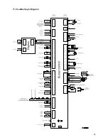
Page 55: ...55 11 5 Ladder Logic Diagram ...

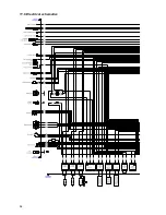
Page 56: ...56 11 6 Electrical schematics ...

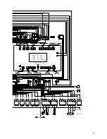
Page 57: ...57 ...

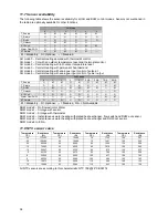
Page 58: ...T_Return O O O O M O O M T_DHW M M M M M M T_Outdoor O O O O O O O 0 10 Volt O O O O O O O O O Water Flow DHW O O O O O M O M M RT Switch O O M O O O O O O M Mandatory O Optional Disabled N A Not Available DHW mode 0 No Domestic Hot Water DHW mode 1 Storage with sensor DHW mode 2 Storage with thermostat DHW mode 3 Instantaneous water heating with plated heat exchanger flow switch and DHW out senso...

Page 59: ...0 Disabled 1 DHW flow sensor 1 Module pump 2 DHW flow switch 2 CH pump 3 CH flow sensor 3 DHW pump 4 CH flow switch 4 System pump 118 Prog Input 3 0 Disabled 5 Cascade pump 1 Drain switch 6 Alarm relay 2 Gas pressure switch 7 Filing valve 122 Prog Input 7 0 Disabled 8 LPG tank 1 T_Flue_2 sensor 9 Ext Igniter 2 T_Flue_2 with blocked flue 10 Air damper 3 Cascade sensor 128 Prog Output 4 0 Disabled 4...

Page 60: ...m selection in Status overview when directly setting Actual setpoint or DHW setpoint Left Return to previous menu item or Status overview Up Directly select Actual setpoint of DHW setpoint in the Status overview push RIGHT to confirm and use UP or DOWN to adjust value Down Directly select Actual setpoint of DHW setpoint in the Status overview push RIGHT to confirm and use UP or DOWN to adjust valu...

Page 61: ...ctly via the Status overview When DHW is active you also cannot set the Actual setpoint CH setpoint directly via the Status overview Press UP DOWN to select the mode then press CONFIRM or RIGHT to confirm the mode and the Actual DHW setpoint becomes directly settable Use UP or DOWN to increase decrease the setpoint Press CONFIRM or RIGHT to confirm your alteration or press ESC or LEFT to cancel A ...

Page 62: ... LEFT If CH mode is set to CH mode 1 CH with an outdoor temperature reset and thermostat control Or CH mode 2 Central Heating with full outdoor temperature reset The following display will appear Enter a menu item by pressing CONFIRM or RIGHT The header shows your location inside the menu as seen in the following image It now is possible to set the Outdoor reset curve by changing the parameters on...

Page 63: ...ettings Boiler 12 2 4 DE AERATION SEQUENCE The De Aeration sequence is a safety function that starts at every power ON and after reset of the boiler and is used to remove the air from the heat exchanger The display will show the following string during DAir sequence Dair Running Dair Error Water Pressure The DAir sequence can be cancelled by the user by pressing the Enter button for over 5 seconds...

Page 64: ... the error codes it receives from the boiler s and if an error code is a new error code the error will be stored in the error log An error will be logged with a real time clock time stamp date and time when the error was detected and a boiler ID of the boiler on which the error was detected The error log can be viewed from the error log menu which is located in the information menu Menu Domestic H...

Page 65: ...e time 2 60 seconds not safety critical Pre ignition time 2 seconds not safety critical Flame failure response time 1 0 second Flame current Minimum 1 0 μA Start detection 1 5 μA Cable length AL BUS1 mm2 AWG Cable length m ft 0 25 23 100 328 1 ft 0 5 20 200 656 2 ft 0 75 18 300 984 3 ft 1 0 17 400 1312 3 ft 1 5 15 600 1968 5 ft 1 This is the total length of the cable not the length between two boi...

Page 66: ...G Appliance type 52 S CBX 155 on Natural Gas Appliance type 53 S CBX 155 on LPG Appliance type 54 Not Used Appliance type 55 Not Used 12 6 Ignition cycle During the ignition cycle multiple safety checks are active False flame detection If flame is detected at the end of the pre spark period Pre ignite a lockout error occurs Re ignition If at the end of the safety period no flame is detected the co...

Page 67: ...AME RECOVERY When the ionization current is too low the system responds by increasing the minimal fan speed in order to keep the flame present This is done by increasing the minimal fan speed when the ionization current is too low Whenever the ionization current is high enough the minimal fan speed will be decreased again When the flame still disappears the minimal fan speed will be increased for ...

Page 68: ...F because the supply temperature reaches CH_Setpoint CH_Hysterese_Up the control will wait a period of time Anti_Cycle_Period 180 sec settable before it is allowed to be switched ON again This function is to prevent short cycling ON and OFF of the boiler However when during the anti cycle wait time the differential between setpoint and supply temperature gets greater than Anti_Cycle_T_Diff anti cy...

Page 69: ...all for heat is blocked and the pumps are stopped There is a fixed hysteresis of 1 C 1 8 F around the Warm_Weather_Shutdown setting This means that the demand is stopped when the outdoor temperature has risen above Warm_Weather_Shutdown 1 C 1 8 F When the outdoor temperature drops below Warm_Weather_Shutdown 1 C 1 8 F again the demand will also start again Boost function The outdoor reset boost fu...

Page 70: ...ather Sets low boiler CH setpoint when outdoor temp is equal to Reset_Curve_Outdoor_Mild_Weather 2 Installer 40 ºC 104 ºF 0 40 ºC 32 104 ºF Reset_Curve_Outdoor_Mild_Weather Sets the outdoor temp at which the boiler setpoint must be low as set by Reset_Curve_Mild_Weather 2 Installer 20 ºC 68 ºF 0 30 ºC 32 86 ºF Reset_Curve_Boiler_Minimum Sets the lower limit for the CH setpoint minimum 2 Installer ...

Page 71: ... using the installer password and changing parameter 28 in the boiler parameters default value is setpoint 4 C Boiler Parameters 25 Warm Weather Shutdn 22 C 26 Boost Temp increment 0 C 27 Boost Time Delay 20 min 28 Night Setback Temp 4 C Adjustable constant Circulation Parameters Parameters Level Default Value Settable CH_Mode 2 Installer 0 Mode 0 5 Warm_Weather_Shutdown Set max outdoor temp Above...

Page 72: ...adverse condition and override control of the analogue signal to prevent an upset condition This means for example that when signal is going up faster than the boiler can regulate that the boiler will slow down to prevent overshoot in temperature The CH_Setpoint_Min and CH_Setpoint_Max parameters can be adjusted to provide the desired temperature adjustment band A heat request will be generated by...

Page 73: ...espond to the minimum modulation rate and the maximum modulation analogue input signal value will correspond to the maximum modulation rate All other safety and control functions associated with the boiler will react normally to adverse condition and override control of the analogue signal to prevent an upset condition A heat request will be generated by an input of 1 5 volts or higher The fan spe...

Page 74: ...ver CH demand but the priority period is limited up to DHW_Max_Priority_Time The priority timer starts when both CH and DHW demand are present After the DHW_Max_Priority_Time is achieved the control will switch from DHW to CH operation CH has priority now for a maximum period of DHW_Max_Priority_Time Different DHW Priority types can be chosen DHW priority Description 0 Time DHW has priority to CH ...

Page 75: ...ºF 40 85 ºC 104 185 ºF DHW_Priority 2 0 Time 1 OFF 2 ON DHW_Max_Priority_Time Sets the maximum time for either DHW or CH priority 2 Installer 60 min DHW_Post_Pump_Period 2 Installer 120 sec 10 900 12 8 4 INSTANTANEOUS WATER HEATING WITH PLATED HEAT EXCHANGER DHW MODE 3 In DHW mode 3 the water flow through a plated heat exchanger is checked with a flow switch If the switch closes a water flow is de...

Page 76: ...rted as well The boiler is PID controlled towards the Boiler_Setpoint When the supply temperature rises above boiler setpoint DHW_Supp_Hysterese_Up the boiler is switched OFF When the Anti_Legionella_Sensor is above Anti_Legionella_Setpoint 3 C 37 F for Anti_Legionella_Burn_Time the controller goes into post circulation and ends the Anti Legionella demand When the controller has powered up the Ant...

Page 77: ...C Installer Set outdoor temperature above which CH demand is locked Bas Outd T 0 30 20 C Installer Set the outdoor temperature at which CH setpoint is set to Bas Supply T Des Outd T 25 25 5 C Installer Set the outdoor temperature at which CH setpoint is set to Des Supply T 2 Domestic Hot Water DHW min max Default unit Access level Description DHW Setpoint 40 71 60 C Installer Set the DHW setpoint ...

Page 78: ...essful Ignitions User Display the number of successful ignitions Failed Ignitions User Display the number of failed ignitions Flame Failures User Display the number of flame losses Operation Days days User Display the total time in operation CH Burner Hours hrs User Display the amount of burn hours for CH DHW Burner Hours hrs User Display the amount of burn hours for DHW 3 4 Error Log min max Defa...

Page 79: ...e zone correction Daylight Savings Time User Select the daylight savings time mode B Display settings min max Default unit Access level Description Time Notation 24h 24h 12h User Select 24h or 12h time notation Date Order User Select the date format Day of Month 2 1 or 2 dig User Select how the day of month is displayed Month User Select how the month is displayed Year 4 2 or 4 dig User Select how...

Page 80: ...i cycling period 9 Anti Cycle Temp Diff 0 20 16 C Installer Set the burner anti cycling differentia 10 Design Supply Temp 4 90 85 C Installer Set CH setpoint when outdoor temperature equals Des Outd T 19 Design Outdoor Temp 25 25 5 C Installer Set the outdoor temperature at which CH setpoint is set to Des Supply T 20 Baseline Supply Temp 4 90 40 C Installer Set CH setpoint when outdoor temperature...

Page 81: ... for the programmable RT input 124 Prog Output 1 0 10 4 Installer Select the function for programmable output 1 125 Prog Output 2 0 10 9 Installer Select the function for programmable output 2 126 Prog Output 3 0 10 6 Installer Select the function for programmable output 3 127 Prog Output 4 0 20 18 Installer Select the function for programmable output 4 128 Mod Pump dT 5 40 20 C Installer Set the ...

Page 82: ...a module is started 144 Hyst Up Quick Stop 0 40 6 C Installer Set the fast hysteresis up after which a module is stopped 145 Hyst Up Stop All 0 60 8 C Installer Set the hysteresis up at which all modules are stopped 146 Number of Units 0 16 1 Installer Set the no of modules expected in the cascade system 147 Power Mode 0 3 2 Installer Set the power mode 148 Max Setp Offset Down 0 20 0 C Installer ...

Page 83: ... the fast hysteresis down after which a boiler is started 164 Hyst Up Quick Stop 0 40 4 C Installer Set the fast hysteresis up after which a boiler is stopped 165 Hyst Up Stop All 0 60 8 C Installer Set the hysteresis up at which all boilers are stopped 166 Number of boilers 0 16 1 Installer Set the number of boilers expected in the cascade system 167 Power Mode 0 3 2 Installer Set the power mode ...

Page 84: ...F and 43 C 77 F boiler input modulates between minimum and maximum At min boiler input ΔT above 43 C 77 F is allowed Hx_Diff_DeltaT_Min 8 C 14 4 F Above ΔT 48 C 86 F the boiler is switched OFF during HX_Diff_Max_Wait_Time Relevant factory set variables Parameter Level Factory Setting Range HX Diff DeltaT Min 3 Factory 35 ºC 63 ºF 10 80 ºC 18 144 ºF HX Diff Max Wait Time Wait time after upper limit...

Page 85: ...res Operation days CH Burner Hours DHW Burner Hours 14 2 Boiler history and time stamps Boiler History Via the boiler history screen in the LabVision PC software the following history data is shown Successful ignitions Failed Ignitions Flame Failures Anti Legionella count Total system run time hr Total CH burn time min Total DHW burn time min Error History The last 15 lockout and 15 blocking error...

Page 86: ...ring or replace Fan if not solved check fuse on PCB or replace PCB 7 FAN_ERROR_ TOO_FAST Fan runs too fast for more than 60 seconds electrical wiring not correctly connected or Fan is malfunctioning Check wiring or replace Fan if not solved check fuse on PCB or replace PCB 8 RAM_ERROR Internal software error wrongly programmed PCB or PB reset PCB or replace PCB and or display unit 9 WRONG_EEPR OM_...

Page 87: ...10 seconds after closing the gas valve wrong earthing of PCB and boiler Check earthing of PCB and boiler 21 FLAME_BEFOR E_IGNIT Flame is detected before ignition wrong earthing of PCB and boiler Check earthing of PCB and boiler 22 TOO_MANY_ FLAME_LOSS Three time flame lost during 1 demand bad gas supply or CO2 level is not correct or bad ignition rod check gas supply pressure check CO2 level and a...

Page 88: ... if not so fill up the system 35 APS_NOT_CLO SED_IN_POST_ PURGE Air pressure switch not closing during post purge 1 no air transport to the burner after heat demand flue or air inlet is blocked or APS is jammed or air signal hose not connected to the air intake pipe or water in hose Check if there are any obstructions in the flue or air intake replace APS if jammed connect air hose to the air inta...

Page 89: ...it Check if the system resistance exceeds the spare capacity of the unit pump 106 REFHI_TOO_HI GH Internal hardware error wrongly programmed PCB or PB reset PCB or replace PCB and or display unit 107 REFHI_TOO_LO W Internal hardware error wrongly programmed PCB or PB reset PCB or replace PCB and or display unit 108 REFLO_TOO_HI GH Internal hardware error wrongly programmed PCB or PB reset PCB or r...

Page 90: ...onnection to PCB or check resistance NTC sensor 127 SUPPLY_SHOR TED Supply sensor shorted malfunctioning supply sensor or short circuiting check connection to PCB or check resistance NTC sensor 129 DHW_SHORTE D DHW sensor shorted malfunctioning DHW sensor or short circuiting check connection to PCB or check resistance NTC sensor 130 FLUE_SHORTE D Flue sensor shorted malfunctioning Flue sensor or s...

Page 91: ...pply voltage too high for more than 60 seconds peak in power supply to boiler check power supply 14 5 Warnings Error no Error Description Cause Solving 200 CC_LOSS_COM MUNICATION Cascade System Managing cascade control lost communication with one of the depending connection between cascaded boilers is interrupted or wiring is broken Check wiring between boiler or distance between boilers is to big...

Page 92: ...rk for cascade the communication busses must be parallel linked together The managing boiler uses the AL bus connection 20 21 for the cascade The depending boilers must be connected to the managing boiler on the 10 11 connection terminals It is important that the power on the 10 11 connection terminals on all dependent boilers is switched to the OFF position see also 15 2 1 All boilers in the casc...

Page 93: ... Module Cascade Settings Change burner address into Managing or Dependent Now select in parameter 147 how many boilers units are in the cascade Boiler address Boiler Operation 0 default 1 2 3 4 Standalone burner 1st boiler managing 2nd boiler depending 3rd boiler depending 4th boiler depending Function of sensor input terminal 3 4 No function System sensor No function No function No function 16 16...

Page 94: ... Cascade CH setpoint adaption When the system temperature is not high enough the setpoint for all boilers will be adjusted The boiler setpoint will be increased when the system temperature drops below Cascade_Setpoint and decreased when it rises above Cascade_Setpoint temperature Dependent Boiler The CH mode for the cascade is defined by the setting of the managing boiler CH mode settings on depen...

Page 95: ...a given interval indicated with parameter Minute_Switch_Priority As soon as the interval has expired the priority switches to CH demand The interval time will be reloaded and priority will switch again after the interval is over 1 CH The priority is permanently given to CH Demand 2 DHW The priority is permanently given to DHW Demand Relevant variables Specific Parameters Level Default Value Range ...

Page 96: ... degrees below the Cascade_Setpoint the burners are started at intervals of Start_Next_Depending_Delay for example 200 seconds Stopping Burners If T_System is Hyst_Up_Stop_Burner degrees above the Cascade_Setpoint the burners are stopped at intervals of Stop_Next_Depending_Delay for example 180 seconds Power balance When T_System is between Hyst_Down_Start_Burner and Hyst_Up_Stop_Burner a power ba...

Page 97: ...st_Up_Stop_All Stop Burner Diff 2 Installer 8 ºC 14 ºF 0 30 ºC 0 54 ºF Hyst_Down_Quick_Start Start Burner Diff in short time 2 Installer 10 ºC 18 ºF 0 20 ºC 0 36 ºF Hyst_Up_Quick_Stop Stop Burner Diff in short time 2 Installer 6 ºC 11 ºF 0 20 ºC 0 36 ºF 15 2 6 CASCADE POWER BALANCE MODE Several different power control modes can be selected to operate the cascade system Power mode 0 Power control d...

Page 98: ...l PID controlled depending in burn state Power Stop_Power_Threshold The managing burner releases another burner for PID control and waits for 3 min Stop_Next_Depending_Delay settable before another burner can be stopped Relevant variables Specific Parameters Level Default Value Range Power Mode 2 Installer 3 0 3 Start_Power_Threshold Threshold rate before starting the next burner Condition at leas...

Page 99: ...lowing conditions When the average burner power of all depending burners is over the set start rate for the next burner o Sum of burner power of all depending Start_Power_Threshold depending in burn Burner shut down The last started burner will be stopped under the following conditions When the average burner power of all depending burners is under the set stop rate for the next burner o Sum of bu...

Page 100: ...parameter First_Depending_To_Start is automatically updated to the next depending When boiler rotation is disabled the parameter First_Depending_To_Start is reset to 0 When the First_Depending_To_Start is manually changed the control will clear all demand of the cascade control After this is will start cascade demand generation with the new selection for First_Depending_To_Start 15 3 1 NEXT DEPEND...

Page 101: ...e setting Emergency_Mode is enabled the control can go into emergency mode when the system sensor status is open or shorted The managing boiler display may show that the system is in emergency mode In emergency mode the system setpoint is set to the Emergency_Setpoint settable via installer menu and all cascaded boilers are allowed to start burning on this setpoint Loss of cascade communication Th...

Page 102: ...Max_Temp_Error 7 Low water cut off 1 error test Simulates the LWCO_1_ Error 8 Low water cut off 2 error test Simulates the LWCO_2_ Error Before running the system test modes first check if the heat can also be dissipated Note that during this mode the supply temperature can be raised above 95 ºC 203 ºF When this temperature is reached the boiler will switch OFF When the supply temperature cools do...

Page 103: ...l heating system Filling water Do not use any additives for the water of the central heating system except glycol The pH value of the water should be more than 5 If this pH value is less please contact the supplier Ensure that any used plastic pipes are oxygen diffusion proof in accordance with DIN 4726 4729 If not make sure that the boiler circuit is separated from the heating circuit by a plate ...

Page 104: ...he gas safety valve for this measurement In chapter 18 1 2 the position of the pressure nipple 3 is shown Min and max gas supply pressures 17 6 Firing for the first time After the commissioning of the boiler and the described previous actions the boiler display will show this screen This screen is active during power up and will remain active until communication with the main Control has been esta...

Page 105: ... Prior to adjustments follow the procedure in 18 3 The fan has been replaced The flue gas check valve has been replaced In any of the cases described always check the gas air ratio of the combustion figure CO2 at maximum and minimum input First set the boiler at maximum load and subsequently at minimum load and repeat if necessary adjustments at maximum load influence values at minimum load and vi...

Page 106: ...Location of the setting screws High Fire venturi adjustment screw use hex key 4 mm 5 32 Allen wrench Low Fire gas valve adjustment screw Torx T40 High Fire screw 2 Low Fire screw 1 Low Fire screw 1 High Fire screw 2 Gas pressure nipple 3 Gas Pressure nipple 3 ...

Page 107: ...he system test automatically stops after 10 minutes after this the system continues with normal demand handling When the system test mode is changed during an active system test the 10 minute timer is restarted Procedure 2 adjust at Low Fire Carry out the next steps 1 Press UP DOWN multiple times to select Low Power Test State Low Power After about 10 seconds the boiler burns at low fire 2 Measure...

Page 108: ...ter 138 will need to be changed on the S CBX boiler to complete the conversion from natural gas to propane LPG There is one main PCB board that does the S CBX 85 105 on both natural gas and LPG supply and one board that does the S CBX 125 155 on both natural gas and LPG Detailed below Option 2 Model Natural Gas Propane S CBX 85 PCB 1 PCB 1 S CBX 105 PCB 1 PCB 1 S CBX 125 PCB 2 PCB 2 S CBX 155 PCB ...

Page 109: ...nd gas combination valve can now be separated The orifice is to be placed between venturi and gas combination valve The rounded side of the orifice must be on the side of the gas combination valve The orifice must be mounted into the gas access of the venturi and secured with the rubber gasket 4 Venturi and gas combination valve now can be reconnected 5 Remount the gas combination valve and the ve...

Page 110: ...e PCB 1 Boiler type Fuel Supply appliance type S CBX 85 Natural Gas 50 S CBX 85 Propane LPG 51 S CBX 105 Natural Gas 52 S CBX 105 Propane LPG 53 PCB 2 Boiler type Fuel Supply appliance type S CBX 125 Natural Gas 50 S CBX 125 Propane LPG 51 S CBX 155 Natural Gas 52 S CBX 155 Propane LPG 53 Confirmation After this perform CO2 adjustments according to the procedures in 18 2 using the values in table ...

Page 111: ...n top of boiler Condensate Drain Check the level of the heat exchanger It must have a slight angle from the rear to ensure that the condensate drains from the heat exchanger YES NO Condensate trap from package installed according installation manual YES NO Inside diameter of drain piping mm inch Is there a definite air gap between the condensate trap and the connection to drain pipe YES NO Total d...

Page 112: ...s supply Type of Gas from installation Is gas isolation valve installed under boiler according to installation manual YES NO Which diameter gas isolation valve is installed Gas piping inside diameter Gas piping material if possible specify mark type Gas piping flexible YES NO YES NO Gas piping inside structure e g smooth corrugated Measured Gas pressure Gas valve Static Measured Gas pressure Gas v...

Page 113: ...ormation Serial number Date and time of maintenance Name of maintenance engineer Which parts were exchanged during maintenance Which settings software were changed during maintenance Special remarks findings Future aspects that need extra attention Additional aspects measurement reports complaints by the end user lock out codes etc Static Gas Pressure CO2 O2 at high fire Gas Pressure at high fire ...

Page 114: ...make more space to dismantle the complete burner unit pull down the burner controller unit To remove this part for an internal heat exchanger check remove the six M6 nuts the ignition cable and the thermal fuse cables Close the gas tap under the boiler and loosen the gas coupling by untighten the swivel joint under the gas valve Remove the air intake pipe from the venturi After this take out the c...

Page 115: ...nd the electrodes into the right position Notice the electrodes undergo high temperatures therefore the electrodes become hard and are difficult to bend While bending used electrodes they might break or burst Check the electrode after bending for any tear crack and signs of rust When they are damaged in any manner or rusty replace the electrode Also replace the electrode when there is a crack in t...

Page 116: ...rner door s thermostat with a torque of 2 Nm Reconnect the wiring Burner door gaskets If any part of a gasket has discoloured changed texture or hardened then the rubber has cured and or has damages these gaskets must be replaced Notice Only use the gaskets that are supplied by the boiler manufacturer Burner door gasket replacement Remove the old gasket Place a new gasket in its groove Respect the...

Page 117: ...e electrodes Remove the braids by sliding under the periphery a thin tool to loosen the braids and remove it Remove and clean the residues of the braids and silicone glue Put a thin string of glue silicone temperature resistant in the seal housing Loctite 5366 or Ottoseal S17 Engage the high temp braided rope and place it in contact of the glue and press the braids Reinstall electrodes Picture 19 ...

Page 118: ...otective film is not sticking anymore on the rear side of this insulation disk To prevent debris from falling in between the coils place a sheet e g paper on the bottom beneath the disk Make the insulation wet by spraying water over it This in order to keep airborne dust to a minimum With a knife cut a cross in the insulation disk avoiding the central insert on the back not visible Make a square c...

Page 119: ...ate Trap Disassemble the condensate trap and clean every part of it Check the condensate trap connection of the heat exchanger for any blocking or pollution and clean it if necessary Check the functioning of the condensate trap by pouring clean tap water in the boiler combustion chamber when burner door is removed This water will exit the heat exchanger by the condensate trap Notice don t wet the ...

Page 120: ...ected checked and replaced Make sure that all these components are mounted correctly before commissioning the boiler again Cleaning the combustion chamber and heat exchanger with acid or alkali products is prohibited 19 2 1 MOUNTING THE BURNER DOOR IMPORTANT Before mounting the burner door make sure that its gaskets and insulation are in excellent shape If any signs of damage or ageing are present...

Page 121: ...ing Record gas pressure and note pressure drop upon start up Record CO2 at high and low fire Visual and Temperature Do visual inspection of all system components and verify programmed temperature settings Connections Check wire connections and make sure they are tight Combustion chamber Check burner tube and combustion chamber coils Clean with nylon brush and vacuum Avoid touching white ceramic fi...

Page 122: ...d user The user should be made familiar with all safety precautions of the boiler and the installation The user should be instructed that service and maintenance of the boiler is required every twelve months Regular service and maintenance is essential for a safe and proper operation of the boiler Hand over the documents supplied with the boiler ...

Page 123: ...Connections Name Wire terminal RT Room thermostat 12 13 FS Flow temperature sensor 3 4 LLH Low loss header High Voltage Connections P1 boiler pump 4 PE 5 P3 system heating pump 6 PE 7 System Example 2 Low Voltage Connections Name Wire terminal OS outdoor temperature sensor 1 2 FS Flow temperature sensor 3 4 LLH Low loss header High Voltage Connections P1 boiler pump 4 PE 5 P3 system heating pump 6...

Page 124: ...ing pump 6 PE 7 System Example 4 Low Voltage Connections Name Wire terminal RT Room thermostat 12 13 FS flow temperature sensor 3 4 OS outdoor temperature sensor 1 2 ST Tank thermostat or sensor 5 6 LLH low loss header T DHW indirect Tank High Voltage Connections P1 boiler pump 4 PE 5 P3 System heating pump 6 PE 7 DV diverter valve 3 way valve 1 2 3 PE P3 P1 HEATING ZONE BOILER OS RT FS LLH DV T L...

Page 125: ...mary pump 2 3 PE P3 System heating pump 6 PE 7 System Example 6 Low Voltage Connections Name Wire terminal RT Room thermostat 12 13 OS outdoor temperature sensor 1 2 FS flow temperature sensor 3 4 SNV non return valve low resistance type LLH low loss header High Voltage Connections P1 boiler pump 4 PE 5 P3 System heating pump 6 PE 7 LLH FS RT P3 P1 HEATING ZONE BOILER OS ST P2 SNV SNV T P1 P1 P1 P...

Page 126: ...thermostat or sensor 5 6 T DHW indirect Tank SNV non return valve low resistance type LLH low loss header High Voltage Connections P1 boiler pump 4 PE 5 P2 HWS primary pump 2 3 PE P3 System heating pump 6 PE 7 P1 P1 P1 P1 P3 LLH FS OS RT SNV SNV SNV SNV BOILER 1 managing HEATING ZONE BOILER 2 depending 1 BOILER 3 depending 2 BOILER 4 depending 3 T P2 SNV SNV ST ...

Page 127: ...tion service or maintenance can cause property damage personal injury exposure to hazardous materials or loss of life Installation and service must be performed by a qualified installer service agency or the gas supplier who must read and follow the supplied instructions before installing servicing or removing this boiler This boiler contains materials that have been identified as carcinogenic or ...

Page 128: ...tatus overview when directly setting Actual setpoint or DHW setpoint Left Return to previous menu item or Status overview Up Directly select Actual setpoint of DHW setpoint in the Status overview push RIGHT to confirm and use UP or DOWN to adjust value Down Directly select Actual setpoint of DHW setpoint in the Status overview push RIGHT to confirm and use UP or DOWN to adjust value Enter Confirm ...

Page 129: ...ing and the following screen appears The De Air sequence is a safety function that starts at every power up and is used to remove the air from the heat exchanger The De Air sequence takes around 14 minutes to complete It can be cancelled by pressing the Enter button for over 5 seconds After completion or manual ending the De Air sequence one of the following Status overview screens appears OR Icon...

Page 130: ...ht part of the PB screen is used to display the error or alert 22 8 2 CHANGING THE DHW SETPOINT DIRECTLY Only applicable if this function is available Press the UP or DOWN button to select the mode 57 0 C is just an example of a possible temperature value Use the left right buttons to move the sign to the front of the temperature digits Use UP DOWN buttons to increase decrease the setpoint Press t...

Page 131: ...ected by a password are only accessible by the installer Passwords are always customer specific and for safety reasons will be provided to the installer only The following menu items require a password Menu item Location inside menu Start up Settings Settings General Settings Other Settings Startup Settings Boiler Parameters Settings Boiler Settings Boiler Parameters Module Cascade Settings Settin...

Page 132: ...e C F DHW Temperature Actual DHW temperature C F DCW Temperature Actual DCW temperature C F Outside Temperature Actual outside temperature C F Flue Temp Actual flue gas temperature C F Flue 2 Temp Actual flue gas 2 temperature C F System Temperature Actual system temperature C F 0 10 V Input Actual 0 10 V input value V Flowrate Actual DHW flowrate l min RT Input Actual RT input status open closed ...

Page 133: ... 12 12 UNIT TYPE Menu Parameter Description Value Unit Metric C bar Select Metric units C bar Imperial F psi Select Imperial units F psi 22 12 13 DATE TIME Menu Parameter Description Value Unit Date Set the current date dd mm yyyy Time Set the current time hh mm Time Zone Settings Enter the time zone settings menu Display Settings Enter the display settings menu 22 12 14 TIME ZONE SETTINGS Menu Pa...

Page 134: ...errors will be stored in the error log An error will be logged with a Real Time Clock time stamp date and time when the error was detected and a boiler ID of the boiler on which the error was detected Note the error log is a completely different error logging mechanism than the one used by the burner controller itself Therefore the error log is different from the internal error history of the burn...

Page 135: ... a service moment will be counted and the Service overdue counter will be stored in the log history It is possible to reset the Service reminder counters before the Service reminder was actually set This should be done when the appliance was serviced before the Service reminder was active This means an overdue counter of 0 hours will be stored on the log which makes sense because the service was n...

Page 136: ...power limited by the CH max power parameter 6 High limit error test Simulates the Max_Temp_Error 7 Low Water Cut Off 1 error test Simulates the LWCO_1_ Error 8 Low Water Cut Off 2 error test Simulates the LWCO_2_ Error Before running the system test modes first check if the heat can also be dissipated Note that during this mode the supply temperature can be raised above 95 ºC 203 ºF When this temp...

Page 137: ......
Page 138: ...22 F 01276 685405 E info strebel co uk I www strebel co uk STREBEL LTD RESERVE THE RIGHT TO CHANGE ANY SPECIFICATIONS ON THIS BOILER RANGE WITHOUT NOTICE Further information on our complete product range is available from our website CAST IRON CONDENSING STEEL SHELL WATER HEATERS RENEWABLES FLUES ACCESSORIES ...

Reviews: