67
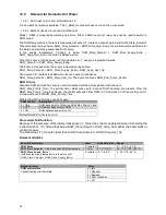
12.6.1 F
LAME DETECTION
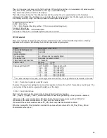
When the boiler is firing, and the flame is not detected anymore, the gas valve will be closed, and the control will
perform a post-purge, after which a restart will take place.
When the flame disappears three times within one heat demand, the control will lockout.
The presence of a flame is measured through the flame rod that points into the flame. Between this pen and earth
an electromagnetic field is present. When a flame is present, the free electrons in the flame flow from the pen to the
earth. This flow of electrons is the flame current.
The flame current is measured by the control as ionization in micro amps (μA).
When the flame current is above Flamerod_Se Flamerod_Hysterese (1.0 μA + 0.5 μA) a flame will be
present. When the flame current is below Flamerod_Setpoint (1.0 μA) the flame will not be present.
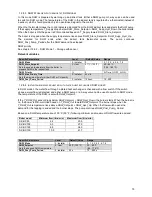
12.6.2 F
LAME RECOVERY
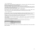
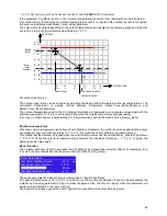
When the ionization current is too low, the system responds by increasing the minimal fan speed, in order to keep
the flame present. This is done by increasing the minimal fan speed when the ionization current is too low.
Whenever the ionization current is high enough, the minimal fan speed will be decreased again. When the flame
still disappears the minimal fan speed will be increased for the next burn cycle.
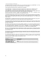
• When the flame current is below Flamerod_Se Flamerod_Delta (1.0 μA + 0.2 μA) the minimal fan speed
will be increased.
• When the flame current is above Flamerod_Se Flamerod Flamerod_Delta * 2 (1.0 μA + 0.2 μA +
0.4 μA) the minimal fan speed will be decreased.
When the flame still disappears the minimal fan speed will be increased for the next burn cycle.
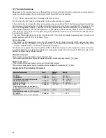
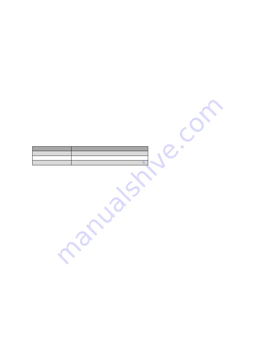
No. of flame losses
Description
0
Minimal fan speed as set in the system
1
In between minimal and ignition fan speed
2
Ignition fan speed
When the system successfully completes a burn cycle, the minimal fan speed will be reset to the set minimal fan
speed in the system.
Summary of Contents for S-CBX 105
Page 2: ......
Page 40: ...40 9 10 Flue Terminal Positioning ...
Page 42: ...42 9 11 1 FIGURE 12 LINE G ...
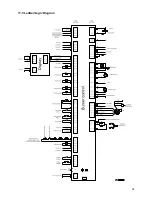
Page 55: ...55 11 5 Ladder Logic Diagram ...
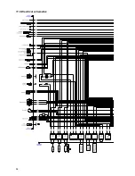
Page 56: ...56 11 6 Electrical schematics ...
Page 57: ...57 ...
Page 137: ......

