70
Setpoint adjustment
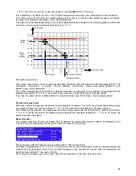
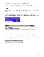
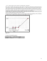
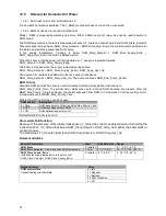
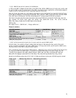
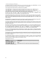
It is possible to adjust the calculated setpoint with parameter CH_Setpoint_Diff. The calculated setpoint can be
increased or decreased with a maximum of 10 ºC (18 °F). The CH setpoint limits (Reset_Curve_Boiler_Minimum
and Reset_Curve_Boiler_Maximum) are respected while adjusting the setpoint.
Apart from the calculated setpoint the functionality is the same as described in chapter 12.7.1.
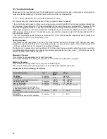
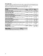
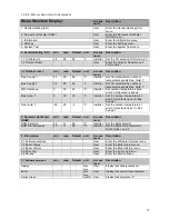
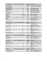
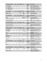
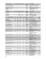
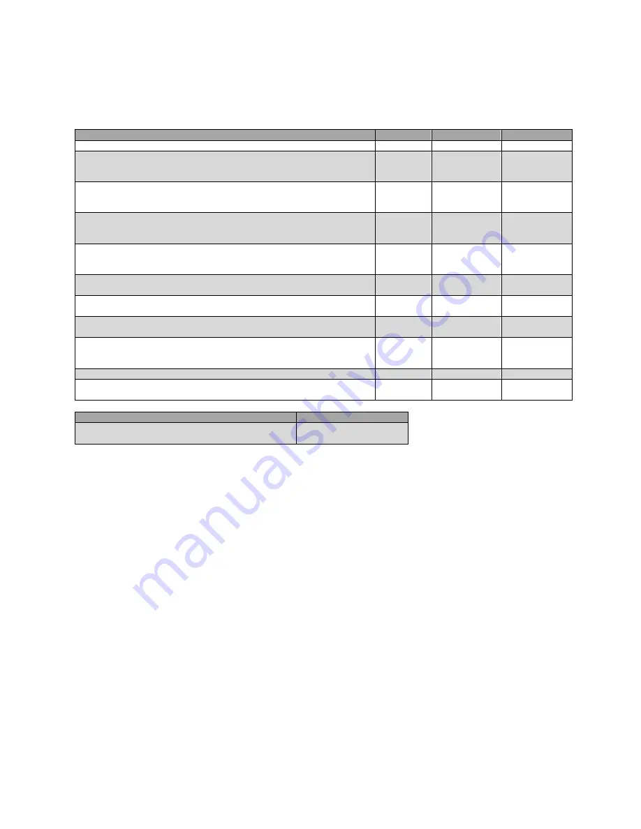
Adjustable Outdoor Reset parameters
Parameters
Level
Default Value Range
CH_Mode
2: Installer
1
Mode 0-5
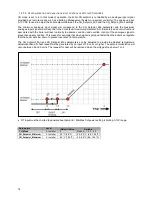
Reset_Curve_Design_Boiler
Sets high boiler CH setpoint when outdoor temp. is equal to
Reset_Curve_Outdoor_Design.
2: Installer
80 ºC (180 ºF)
0…..80 ºC
(32…..176 ºF)
Reset_Curve_Outdoor_Design
Sets the outdoor temp at which the boiler setpoint must be high as set by
Reset_Curve_Design_Boiler.
2: Installer
-5 ºC (23 ºF)
-20…..5 ºC
(-4…..41 ºF)
Reset_Curve_Boiler_Mild_Weather
Sets low boiler CH setpoint when outdoor temp. is equal to
Reset_Curve_Outdoor_Mild_Weather.
2: Installer
40 ºC (104 ºF)
0…..40 ºC
(32…..104 ºF)
Reset_Curve_Outdoor_Mild_Weather
Sets the outdoor temp at which the boiler setpoint must be low as set by
Reset_Curve_Mild_Weather.
2: Installer
20 ºC (68 ºF)
0…..30 ºC
(32…..86 ºF)
Reset_Curve_Boiler_Minimum
Sets the lower limit for the CH setpoint (minimum).
2: Installer
30 ºC (86 ºF)
20…..90 ºC
(68…..194 ºF)
Reset_Curve_Boiler_Maximum
Sets the upper limit for the CH setpoint (maximum).
2: Installer
90 ºC (176 ºF)
20…..90 ºC
(68…..194 ºF)
Warm_Weather_Shutdown
Set max. outdoor temp. Above this temperature heat demand is blocked.
2: Installer
22 ºC (72 ºF)
0…..35 ºC
(32…..100 ºF)
Boost_Temperature_Incr
CH setpoint increment when heat demand remains beyond
Boost_Time_Delay.
2: Installer
0 ºC (32 ºF)
0…..20 ºC
(0…..68 ºF)
Boost_Time_Delay
2: Installer
20 min.
1 – 120 min.
CH_Setpoint_Diff
Adjusts the calculated CH setpoint.
1: User
0 ºC (0 ºF)
-10…..10 ºC
(-18…..18 ºF)
Status variables
Range
Actual_CH_Setpoint
Calculated CH setpoint, based on outdoor reset curve.
20.....90 ºC
(68...194 ºF)
Summary of Contents for S-CBX 105
Page 2: ......
Page 40: ...40 9 10 Flue Terminal Positioning ...
Page 42: ...42 9 11 1 FIGURE 12 LINE G ...
Page 55: ...55 11 5 Ladder Logic Diagram ...
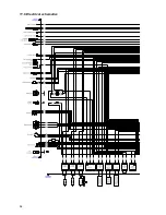
Page 56: ...56 11 6 Electrical schematics ...
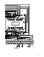
Page 57: ...57 ...
Page 137: ......

