79
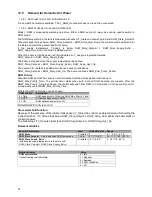
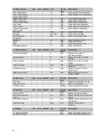
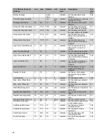
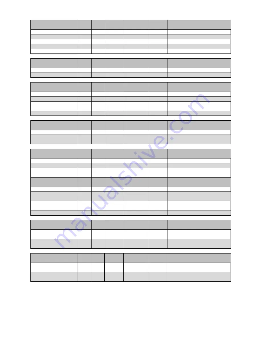
4.1 General settings
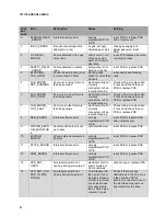
min. max. Default unit
Access
level
Description:
4.1.1 Language
User
Enter the Language menu
4.1.2 Unit Type
User
Enter the Unit Type menu
4.1.3 Date & Time
User
Enter the Date & Time menu
4.1.4 Cascade Mode
User
Enter the Cascade Mode menu
4.1.5 Other Settings
User
Enter the Other Settings menu
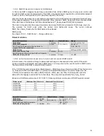
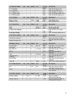
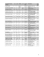
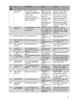
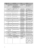
4.1.2 Unit type
min. max. Default unit
Access
level
Description:
Metric (˚C, bar)
˚C/bar
˚C/bar
User
Select Metric units
Imperial (˚F, psi)
x
˚F/psi
User
Select Imperial units
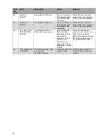
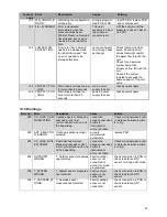
4.1.3 Date & Time
min. max. Default unit
Access
level
Description:
Date
dd-mm-yy
User
Set the current date
Time
hh:mm
User
Set the current time
A. Time Zone Settings
User
Enter the time zone settings
menu
B. Display Settings
User
Enter the display settings menu
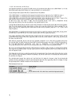
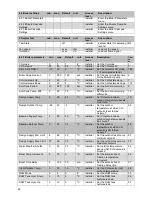
A Time Zone Setting
min. max. Default unit
Access
level
Description:
Time Zone Correction
User
Set the time zone correction
Daylight Savings Time
User
Select the daylight savings time
mode
B Display settings
min. max. Default unit
Access
level
Description:
Time Notation
24h
24h/12h
User
Select 24h or 12h time notation
Date Order
User
Select the date-format
Day of Month
2
1 or 2 dig.
User
Select how the day of month is
displayed
Month
User
Select how the month is
displayed
Year
4
2 or 4 dig.
User
Select how the year is displayed
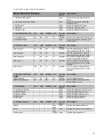
Date Separation
Character
User
Select the date separation
character
Day of Week
User
Select how the day of week is
displayed
Seconds
no
yes/no
User
Select if seconds are displayed
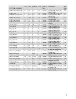
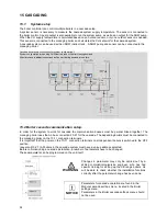
4.1.4 Cascade mode
min.
max.
Default
unit
Access
level
Description:
Full
Full
Full
Installer Select full cascade mode for
more data for max 8 boilers
Basic
Installer Select basic cascade mode for
9 to 16 boilers
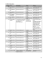
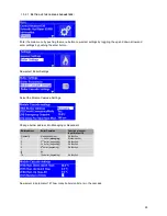
4.1.5 Other settings
min. max. Default unit
Access
level
Description:
Modbus Address
0
255
1
0…255
User
Select the Modbus
communication address
Modbus Stop bits
1
2
2
1 – 2
User
Select the number of Modbus
communication stop bits
Summary of Contents for S-CBX 105
Page 2: ......
Page 40: ...40 9 10 Flue Terminal Positioning ...
Page 42: ...42 9 11 1 FIGURE 12 LINE G ...
Page 55: ...55 11 5 Ladder Logic Diagram ...
Page 56: ...56 11 6 Electrical schematics ...
Page 57: ...57 ...
Page 137: ......

