81
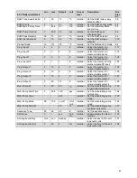
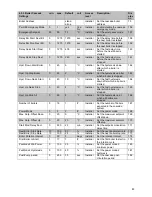
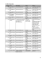
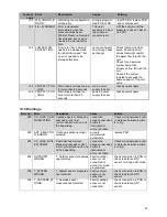
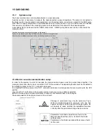
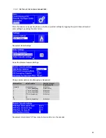
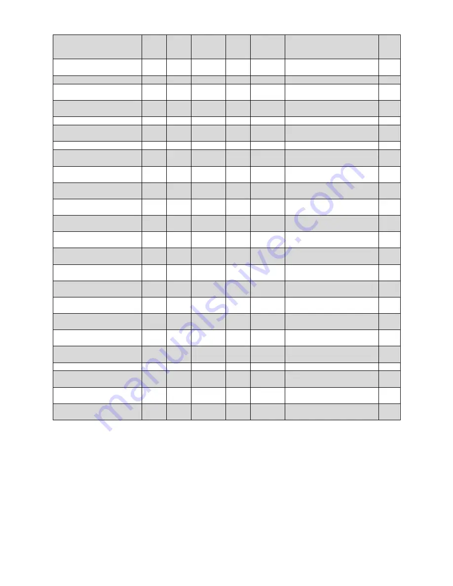
4.2.1 Boiler parameters
min.
max.
Default
unit
Access
level
Description:
Dis
play
nr:
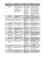
DHW Tank Supply Extra
0
30
15
⁰
C
Installer Set the DHW tank supply
setpoint offset
38
DHW Priority
0
2
on
0-2
Installer Set the DHW priority mode 42
DHW Max. Priority Time
1
255
60
min.
Installer Set the maximum DHW
priority time
43
DHW Pump Overrun
0
900
20
sec.
Installer Set the DHW post-
circulation time
44
DHW/Tank Setpoint
39
70
60
⁰
C
Installer Set the DHW setpoint
48
DHW Store Setpoint
0
10
65
⁰
C
Installer Set the DHW storage
setpoint
115
Preheat mode
on
off
off
⁰
C
Installer Set the PreHeat Eco mode 64
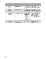
Prog. Input 2.
0
4
2
#
Installer Select the function for
programmable input 2
117
Prog. Input 3.
0
2
2
#
Installer Select the function for
programmable input 3
118
Prog. Input 7.
0
5
3
#
Installer Select the function for
programmable input 7
122
Prog. Input RT.
0
1
1
#
Installer Select the function for the
programmable RT input
124
Prog. Output 1.
0
10
4
#
Installer Select the function for
programmable output 1
125
Prog. Output 2.
0
10
9
#
Installer Select the function for
programmable output 2
126
Prog. Output 3.
0
10
6
#
Installer Select the function for
programmable output 3
127
Prog. Output 4.
0
20
18
#
Installer Select the function for
programmable output 4
128
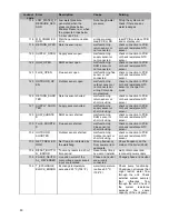
Mod. Pump dT
5
40
20
⁰
C
Installer Set the modulating pump
target delta temperature
133
Mod. Pump Start Time
0
255
120
sec.
Installer Set the modulating pump
start up time
134
Mod. Pump Type
wilo
Installer Set the modulating pump
model
135
Mod. Pump Mode
20
100
on/off
o/f or
mod.
Installer Set the modulating pump
mode
136
Mod. Pump Min Pwr
30
%
Installer Set the modulating pump
minimum duty cycle
137
Appliance Type
50
55
50
#
Installer Set the appliance type
138
Dair active
0
1
yes
Yes/
No
Installer Enable/disable the De-Air
function
139
Anti Legionella Day
mon sun
Sunday
Installer Select the day for the anti-
legionella cycle
107
Anti Legionella Hour
0
23
0
hrs.
Installer Select the time for the anti-
legionella cycle
108
Summary of Contents for S-CBX 105
Page 2: ......
Page 40: ...40 9 10 Flue Terminal Positioning ...
Page 42: ...42 9 11 1 FIGURE 12 LINE G ...
Page 55: ...55 11 5 Ladder Logic Diagram ...
Page 56: ...56 11 6 Electrical schematics ...
Page 57: ...57 ...
Page 137: ......

