83
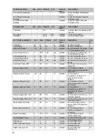
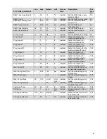
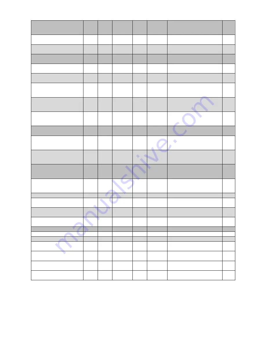
4.2.3 Boiler Cascade
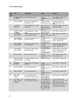
Settings
min. max. Default unit
Access
level
Description:
Dis
play
nr:
Boiler Address
stand
alone
Installer Set the cascade boiler
address
73
Permit Emergency Mode
0
1
yes
Yes/
No
Installer Enable/disable the cascade
emergency mode
156
Emergency Setpoint
20
90
70
°C
Installer Set the emergency mode
setpoint
157
Delay Per Start Next Blr
0
1275 1275
sec.
Installer Set the delay time before
the next boiler is started
158
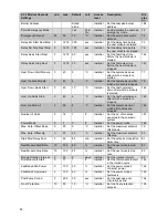
Delay Per Stop Next Blr.
0
1275 1275
sec.
Installer Set the delay time before
the next boiler is stopped
159
Delay Quick Start Next
0
1275 400
sec.
Installer Set the fast delay time
before the next boiler is
started
160
Delay Quick Stop Next
0
1275 240
sec.
Installer Set the fast delay time
before the next boiler is
stopped
161
Hyst. Down Start Boiler
0
40
5
°C
Installer Set the hysteresis down
after which a boiler is
started
162
Hyst. Up Stop Boiler
0
40
2
°C
Installer Set the hysteresis up after
which a boiler is stopped
163
Hyst. Down Quick Start
0
40
10
°C
Installer Set the fast hysteresis
down after which a boiler is
started
164
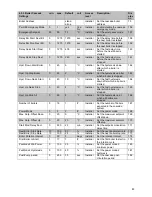
Hyst. Up Quick Stop
0
40
4
°C
Installer Set the fast hysteresis up
after which a boiler is
stopped
165
Hyst. Up Stop All
0
60
8
°C
Installer Set the hysteresis up at
which all boilers are
stopped
166
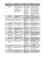
Number of boilers
0
16
1
#
Installer Set the number of boilers
expected in the cascade
system
167
Power Mode
0
3
2
#
Installer Set the power mode
168
Max. Setp. Offset Down
0
20
0
°C
Installer Set the maximum setpoint
offset down
169
Max. Setp. Offset Up
0
20
20
°C
Installer Set the maximum setpoint
offset up
170
Start Mod. Delay Fact.
0
255
20
min.
Installer Set the setpoint modulation
delay time
171
Next Boiler Start Rate
10
100
80
%
Installer Set the next boiler start rate 172
Next Boiler Stop Rate
10
100
25
%
Installer Set the next boiler stop rate 173
Boiler Rotation Interval
0
30
5
days Installer Set the rotation interval
174
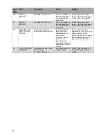
First Boiler to Start
1
17
1
#
Installer Set the first boiler to start in
the rotation cycle
175
PwrMode2 Min Power
0
100
20
%
Installer Set the power mode 2
minimum power
180
PwrMode2 Hysteresis
0
100
40
%
Installer Set the power mode 2
hysteresis
181
Post-Pump period
0
255
30
sec.
Installer Set the cascade post-
circulation period
182
Summary of Contents for S-CBX 105
Page 2: ......
Page 40: ...40 9 10 Flue Terminal Positioning ...
Page 42: ...42 9 11 1 FIGURE 12 LINE G ...
Page 55: ...55 11 5 Ladder Logic Diagram ...
Page 56: ...56 11 6 Electrical schematics ...
Page 57: ...57 ...
Page 137: ......

