85
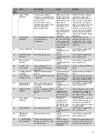
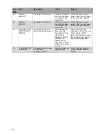
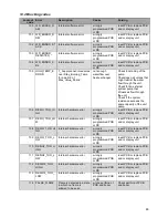
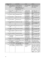
14 ERROR INFORMATION.
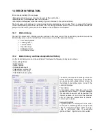
Errors can be divided in three groups:
• Manual reset locking errors (can only be reset by the reset button).
• Blocking errors (will disappear when error is gone)
• Warnings (will disappear when the warning is gone, not stored in the controls e2prom)
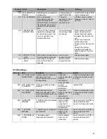
The boiler pump will continue to run during most locking and blocking error codes. This is to prevent the freezing
of the Central Heating circuit when the boiler is in error during the winter period. For some non-volatile lockouts the
pump will not be running, also see the error tables in this chapter for more details.
14.1 Boiler history.
The last 15 lockouts and 15 blocking errors are stored in the boiler control. This boiler history can be shown via the
Boiler History screen via the installer boiler status menu in one of the advanced displays.
•
Successful ignitions
•
Failed Ignitions
•
Flame Failures
•
Operation days
•
CH Burner Hours
•
DHW Burner Hours
14.2 Boiler history and time stamps Boiler History
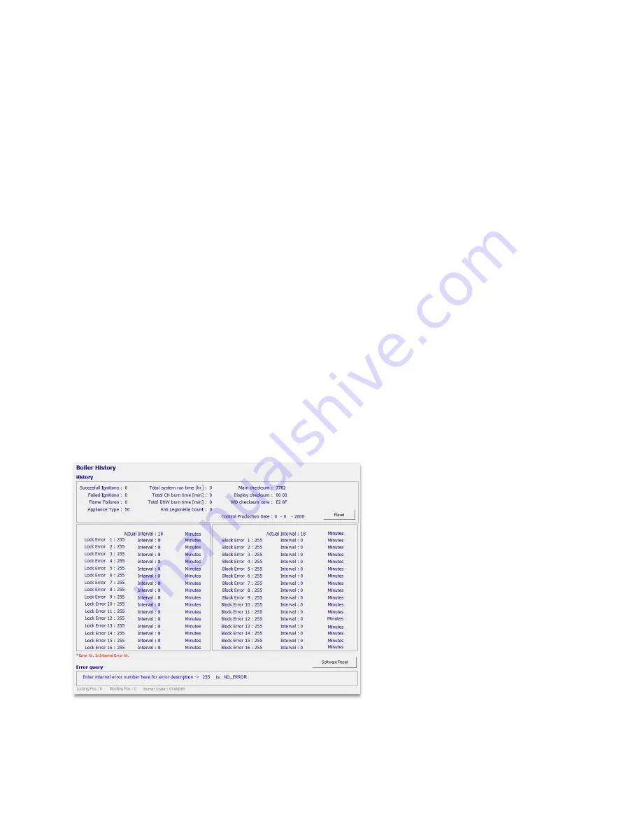
Via the ‘boiler history’ screen in the LabVision PC software the following history data is shown:
• Successful ignitions
• Failed Ignitions
• Flame Failures
• Anti-Legionella count
• Total system run time [hr]
• Total CH burn time [min]
• Total DHW burn time [min]
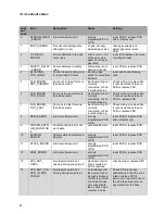
Error History
The last 15 lockout and 15 blocking errors are
stored in the boiler control. This boiler history
can be shown via the Boiler History screen via
the installer boiler status menu in one of the
advanced displays.
Time Stamp
A time stamp will be added to an error at the
moment the error occurs. The time between
this error and a new error will be counted. The
interval between an error and the previous
error is shown as interval time in minutes,
hours, days or weeks.
Successful ignitions
To prevent wear on the e2prom of the boiler
control, the successful ignitions are only saved
after 16 successful ignitions. When a power
cycle is performed after 15 successful
ignitions, these 15 ignitions are not counted.
Summary of Contents for S-CBX 105
Page 2: ......
Page 40: ...40 9 10 Flue Terminal Positioning ...
Page 42: ...42 9 11 1 FIGURE 12 LINE G ...
Page 55: ...55 11 5 Ladder Logic Diagram ...
Page 56: ...56 11 6 Electrical schematics ...
Page 57: ...57 ...
Page 137: ......

