97
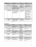
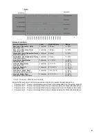
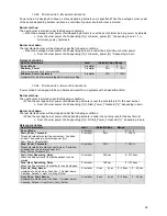
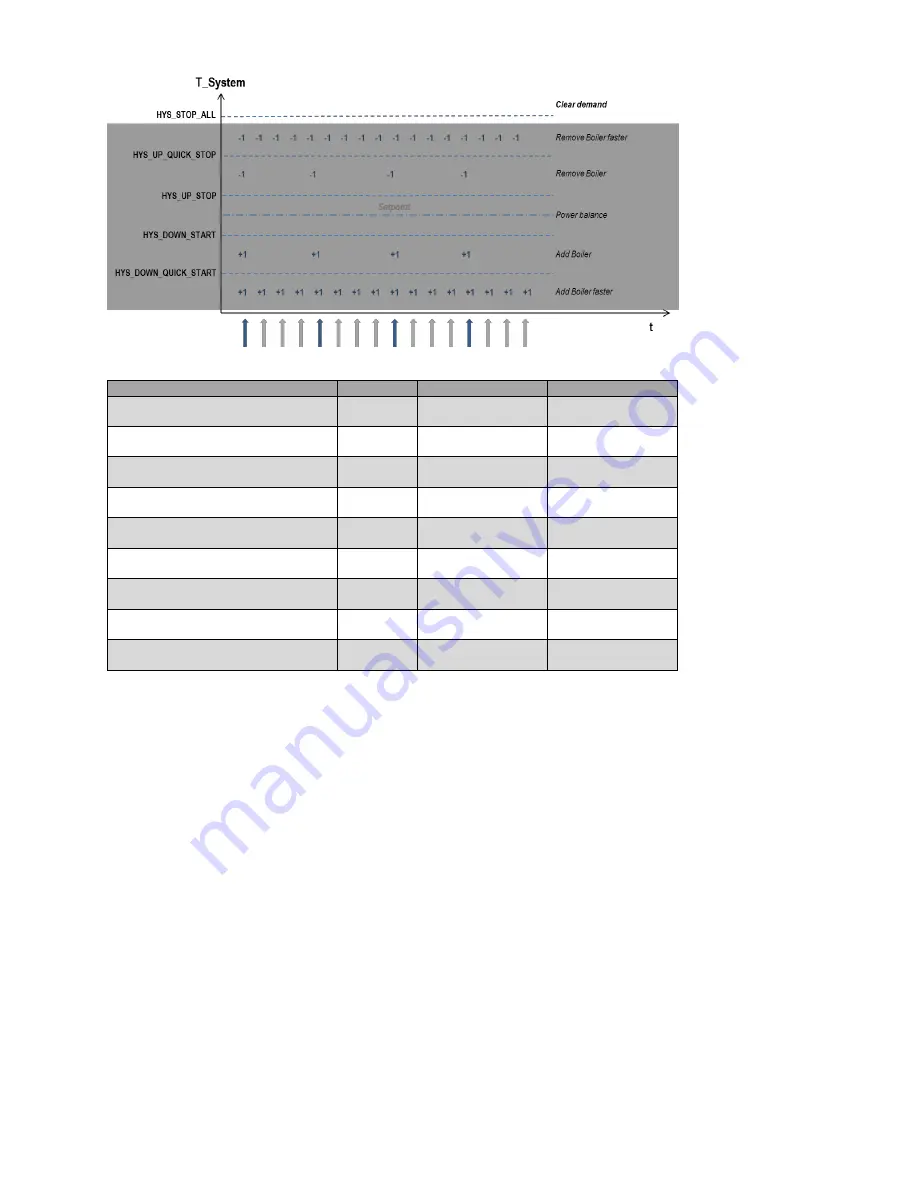
Relevant variables
Specific Parameters
Level
(Default) Value
Range
Start_Next_Depending_Delay
Start Delay Time
2: Installer
200 (sec)
0…1275
Stop_Next_Depending_Delay
Stop Delay Time
2: Installer
180 (sec)
0…1275
Quick_Start_Next_Depending_Delay
Quick Start Interval
2: Installer
50 (sec)
0…1275
Quick_Stop_Next_Depending_Delay
Quick Stop Interval
2: Installer
30 (sec)
0…1275
Hyst_Down_Start_Burner
Start Burner Diff
2: Installer
5 ºC (9 ºF)
0...20 ºC
(0...36 ºF)
Hyst_Up_Stop_Burner
Stop Burner Diff
2: Installer
4 ºC (7 ºF)
0...20 ºC
(0...36 ºF)
Hyst_Up_Stop_All
Stop Burner Diff
2: Installer
8 ºC (14 ºF)
0…30 ºC
(0…54 ºF)
Hyst_Down_Quick_Start
Start Burner Diff in short time
2: Installer
10 ºC (18 ºF)
0...20 ºC
(0...36 ºF)
Hyst_Up_Quick_Stop
Stop Burner Diff in short time
2: Installer
6 ºC (11 ºF)
0...20 ºC
(0...36 ºF)
15.2.6 C
ASCADE
–
P
OWER BALANCE MODE
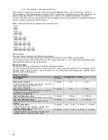
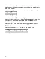
Several different power control modes can be selected to operate the cascade system.
• Power mode 0: Power control disabled, each boiler modulates based on the system setpoint.
• Power mode 1: Power control algorithm to have a minimum amount of boilers/boilers active.
• Power mode 2: Power control algorithm to have a maximum amount of boilers/boilers active.
• Power mode 3: Power control algorithm to have a balanced amount of boilers/boilers active.
Summary of Contents for S-CBX 105
Page 2: ......
Page 40: ...40 9 10 Flue Terminal Positioning ...
Page 42: ...42 9 11 1 FIGURE 12 LINE G ...
Page 55: ...55 11 5 Ladder Logic Diagram ...
Page 56: ...56 11 6 Electrical schematics ...
Page 57: ...57 ...
Page 137: ......

