background image

ESR-Auto Plus

®

 and ESR-657 Mixer Dismantling Guideline 

Jan. 2009, 880010-1 

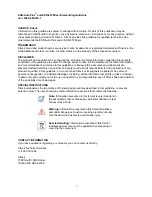
Warning: 

Information presented in this format identifies a 

potentially dangerous situation involving electrical circuitry. 
Use the advice in this text to avoid bodily injury. 

Note: 

Information presented in this format is very important in 

the associated context. Please pay particular attention to text 
conveyed as a Note. 

Special Handling:

 Information presented in this format 

indicates special care must be applied when disposing or 
recycling the component. 

SOURCE: Streck 

Information in this guideline is subject to change without notice. No part of this publication may be 
reproduced or distributed in any form or by any means, electronic or mechanical, for any purpose, without 
the express written permission of Streck.  Streck provides this guideline for qualified technicians who 
must dismantle the ESR-Auto Plus and/or ESR-657 Mixer. 

 
TRADEMARKS 

Streck brand and product names are service marks, trademarks or registered trademarks of Streck in the 
United States and other countries. All other marks are the property of their respective owners. 

 
DISCLAIMER 

The products and specifications, configurations, and other technical information regarding the products 
contained in this guideline are subject to change without notice. All the statements, technical information, 
and recommendations contained in this guideline are believed to be accurate and reliable but are 
presented without warranty of any kind, and users must take full responsibility for the application of any 
products specified in this guideline. In no event shall Streck or its suppliers be liable for any indirect, 
special, consequential, or incidental damages, including, without limitation, lost profits or loss or damage 
to data or property arising out of the use or inability to use this guideline, even if Streck has been advised 
of the possibility of such damages.  

 
SPECIAL INSTRUCTIONS 

Streck emphasizes the importance of following all procedures described in this guideline, to prevent 
personal injury. The user should pay careful attention to sections that contain the following: 


CONTACT INFORMATION 

If you have questions regarding our products you can contact us directly: 
 
Streck Technical Services 
+1.402.333.1982 
 
Streck 
7002 South 109th Street 
Omaha, NE USA 68128 


Summary of Contents for ESR-Auto Plus

Page 1: ...ntries All other marks are the property of their respective owners DISCLAIMER The products and specifications configurations and other technical information regarding the products contained in this guideline are subject to change without notice All the statements technical information and recommendations contained in this guideline are believed to be accurate and reliable but are presented without...

Page 2: ... CONTENTS ESR Auto Plus Dismantling Instructions General Preparation 1 Main Cover Removal 1 LED Photo Eye Board Removal 2 Main Board Position LED Board Removal 3 Printer Board Removal 4 ESR 657 Mixer Dismantling Instructions General Preparation 5 Power Cord Adapter Removal 5 ...

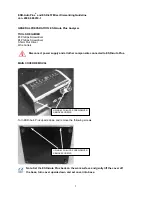
Page 3: ... Wire Cutters MAIN COVER REMOVAL Turn ESR Auto Plus upside down and remove the following screws Disconnect power supply and all other components connected to ESR Auto Plus USING 3 PHILLIPS SCREWDRIVER REMOVE SCREWS USING 3 PHILLIPS SCREWDRIVER REMOVE SCREWS Note Set the ESR Auto Plus back on the work surface and gently lift the cover off the base turn cover upside down and set cover into base ...

Page 4: ...010 1 2 LED PHOTO EYE BOARD REMOVAL Disconnect all 9 connections 1 3 4 5 6 7 8 9 2 1 USING 4 PHILLIPS SCREWDRIVER REMOVE SCREWS REMOVE PLATE AND GUIDE TUBES 2 SLIDE SHUTTLE ASSEMBLY OFF AND REMOVE BOARDS 3 USING 3 PHILLIPS SCREWDRIVER REMOVE SCREWS AND CIRCUIT BOARDS ...

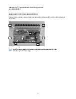
Page 5: ...0010 1 3 MAIN BOARD POSITION LED BOARD REMOVAL Using a 5 5mm nut driver remove 3 nuts from the position LED board 1 3 and 5 nuts from the main board 4 8 1 2 3 4 5 6 7 8 Note Carefully remove the position LED board and the main board These boards may have sharp edges ...

Page 6: ...AL Using a 5 5mm nut driver remove 3 nuts from the printer bracket 1 3 and remove printer bracket Using 3 Phillips screwdriver remove 3 screws 1 3 2 1 3 1 3 2 1 USING WIRE CUTTERS CUT WIRES HERE 2 UNPLUG CONNECTOR HERE Properly recycle or dispose of all circuit boards and power supply adapters ...

Page 7: ...g Guideline Jan 2009 880010 1 5 GENERAL PREPARATION ESR 657 Mixer TOOLS REQUIRED No tools required POWER CORD REMOVAL Disconnect power supply from ESR 657 Mixer DISCONNECT POWER SUPPLY CABLE Properly recycle or dispose of power cord and adapter ...

Reviews: