8
Copyright © 2019 StreetStrider International, LLC
Assembling the
StreetStrider 8s
Unpacking and Prep (see video)
3
3.1
To assemble your
StreetStrider 8s
, first follow the steps and photos in this manual and view the
StreetStrider 8s
assembly videos where
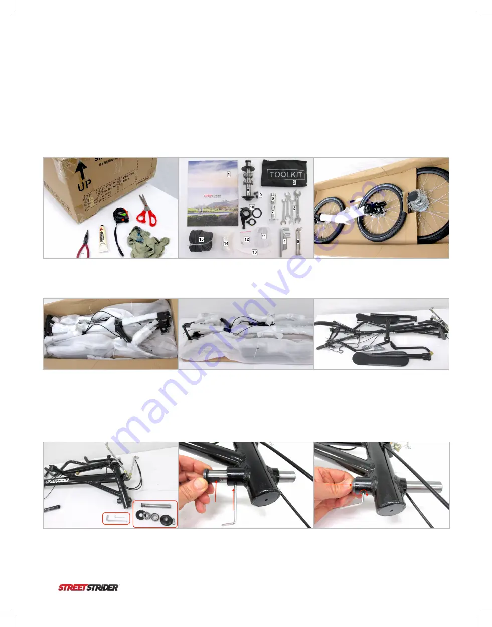
indicated. Included in the shipping box are the
StreetStrider 8s
in parts, an Owner’s Manual [1] and a small bundle in the top tray inside the
box containing a tool kit [2] which includes, four open end wrenches 17 x 14, 15 x 13, 14 x 12, and 13 x 10 mm [3], seven hex wrenches 8,
6, 5, 4, 3, 2.5, 2 [4], two tire levers [5], a 19 mm front hub socket [6], and a front wheel caster spanner wrench [7]. The parts bags contain the
front beam shaft assembly [8], a right crank arm screw [9], the shifter cassette parts [10], three wheel reflectors [11], two front brake cable
tips [12], zip ties [13], touch up paint [14], and two spare inner tubes [15],
Figure 3.1.2.
Figure 3.1.1
The
StreetStrider
box shows which
side is up. You will need a blade or scissors,
pliers, tape measure, grease and a rag.
Figure 3.1.4
The main frame assembly,
padded and secured with zip ties, is on the
bottom cardboard panel which has corner
cut-outs.
Figure 3.1.2
The top tray in the box holds
the parts bundle and the support layers
underneath protect the
StreetStrider
.
Figure 3.1.5
Grip the corner cut-outs and
lift that panel and the folded StreetStrider
out of the box, set the unit on a table, and
remove the remaining zip ties.
Figure 3.1.3
The front wheel assembly and
rear wheel are the next 2 layers. Remove the
wheels and set aside.
Figure 3.1.6
Once all the packing is removed
set the foot platform assemblies (lower pole,
ski, foot platform, crank arm) aside.
Front Wheels (see video)
3.2
Figure 3.2.1
Lay the frame on it’s left side.
Retrieve the front beam shaft assembly,
take the cap, tapered bearings and back
plate off the shaft, and get the 8 and 3 mm
hex wrenches.
Figure 3.2.2
Loosen the set screw under
the front beam shaft tube with a 3 mm hex
wrench. Slide the shaft into the tube so that
the flat section on the rear end of the shaft
fits just above the 3 mm.
Figure 3.2.3
With the shaft inserted all the way
forward, secure the shaft by tightening the set
screw with the 3 mm hex wrench.


