6.4.4
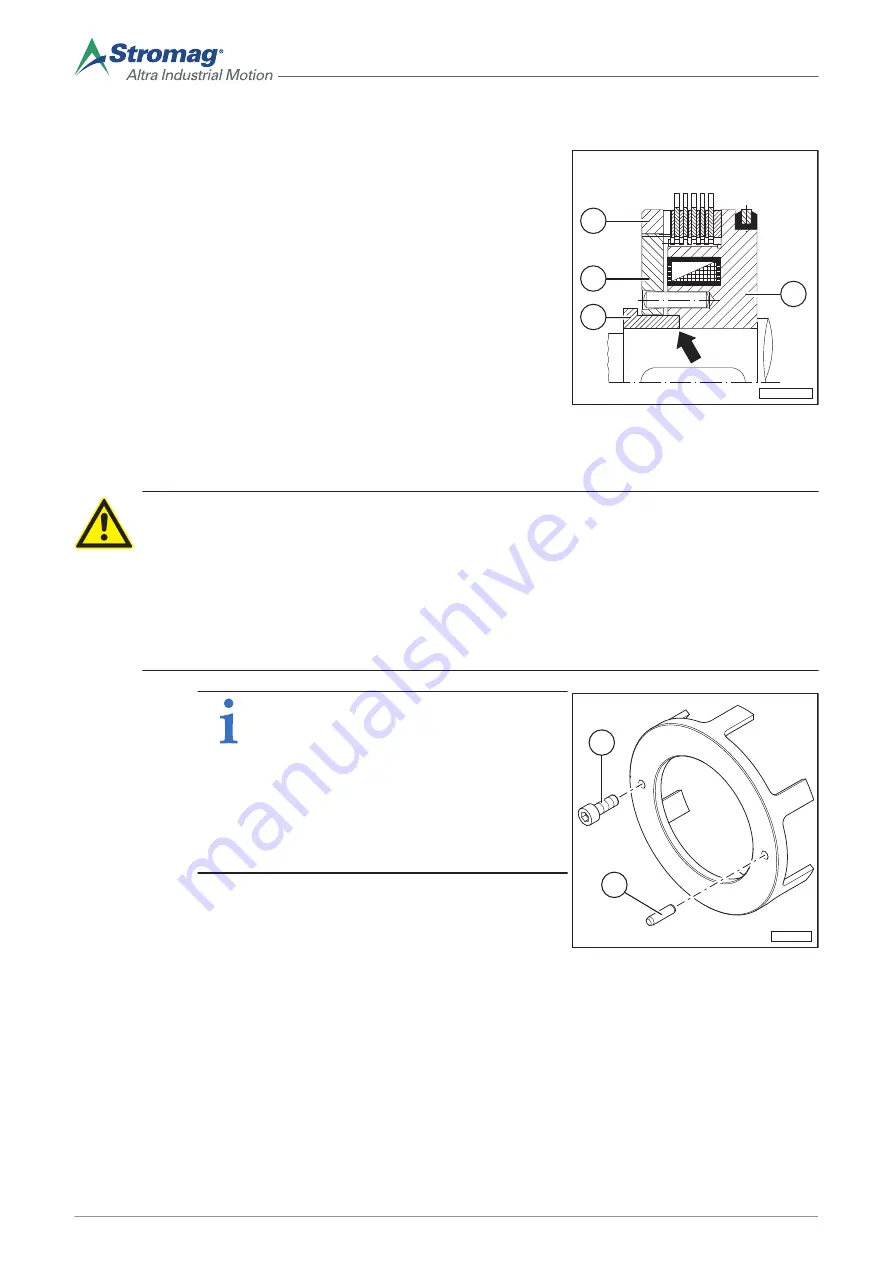
Mounting the armature plate
Assembly of the
armature plate
1. Insert the sleeve (3) in the armature plate (4) with
adjusting nut (5).
2. Position the sleeve (3) on the parallel key (mating
part of the customer's machine) and slide the entire
armature plate (4) and adjusting nut (5) up to the
stop (arrow) in the coil body (2).
5
2
4
SKB-0124_04
3
Fig. 15
6.4.5
Mounting the outer body
ATTENTION
Damage to the clutch due to defective adjacent construction
A defective adjacent construction may cause component movements that are not permitted. The
sleeve must not show any axial play on the shaft, as it presents the guiding and lifting limit of the ar-
mature plate.
► The mounting dimensions according to the dimensional drawing must be observed.
► The outer body must be fixed in the same way as the sleeve in installed condition.
Preparing the
outer body
NOTE
The figure shows two installation examples.
The outer body can be fixed with screws
(113) or bolts (114). The type and location of
the fixing points must be chosen by the ma-
chine manufacturer.
The mandatory dimensions can be obtained
from the order-specific dimensional drawing
of the clutch.
1. Make the fixing points in the outer body.
SKB-0145
113
114
Fig. 16
30
Mounting instructions Electromagnetic multi-disc clutch EKE/EKB, EDE/EDB • No. 500-00000 C • 10/2017
Summary of Contents for EDB Series
Page 2: ......
Page 6: ...VI Montageanleitung Elektromagnet Lamellenkupplung EKE EKB EDE EDB Nr 500 00000 C 10 2017 ...
Page 54: ......


