background image


Stromberg


Carlson


Products,


Inc.


2323


Traversefield


Drive


Traverse


City,


Michigan


49686


231

947

8600


ext.


108


for


Customer


Service


info@strombergcarlson.com


Assembly


Instructions


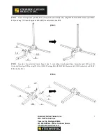
STEP


1


Assemble


the


primary


frame


by


connecting


the


Short


Support


Base


Assembly


(part


#1)


and


(2)


Horizontal


Arms


(part


#2),


using


(2)


5/16"


knob,


(4)


5/16"


flat


washer


,


(2)


5/16"


spring


washer,


(2)


5/16"


hexagon


bolt,


(2)


M10


Carriage


bolts


and


(2)


M10


Locknuts


(parts


#3,


#4,


#5,#6,#27&


#28).


See


FIG.


1


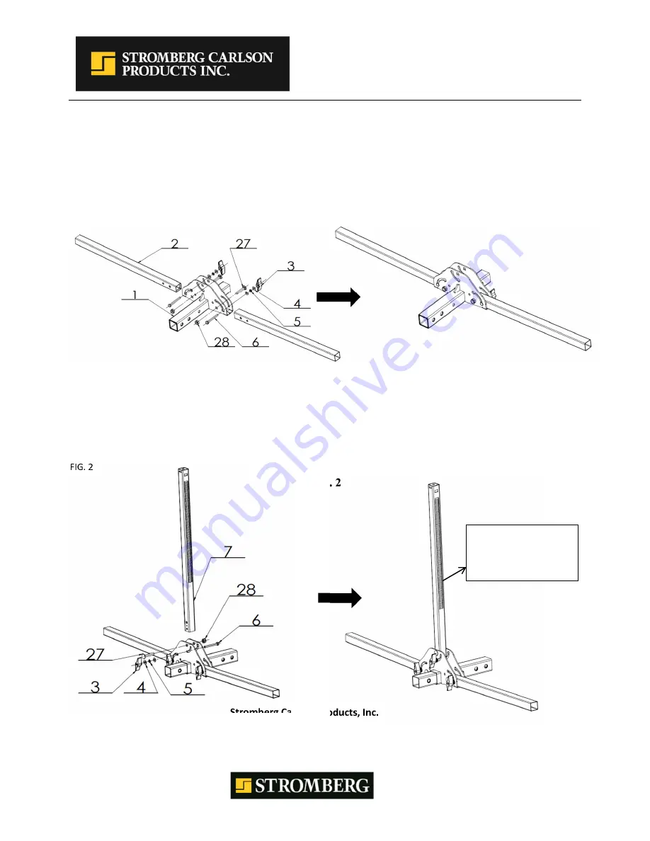
FIG. 1 


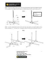
STEP


2


Place


Vertical


Arm


(part


#7)


into


the


Short


Support


Base


Assembly


by


using


M10


Carriage


Bolt


and


M10


Locknut


(parts


#27


&


#28).


With


the


Vertical


Tube


in


a


vertical


position,


insert


the


5/16"


hexagon


bolt


(part


#6),


through


the


5/16"


flat


washer(part


#4)


,the


5/16"


spring


washer(part


#5)


and


the


5/16"


flat


washer(part


#4)


,tighten


with


5/16"


knob


(part


#3)


.See


FIG.


2


FIG. 2 


NOTICE: 
The sliding teeth face 
this direction 

Summary of Contents for BC-204

Page 1: ...ity Michigan 49686 231 947 8600 ext 108 for Customer Service info strombergcarlson com 1 PLATFORM BIKE CARRIER Model BC 204 MAXIMUM LOADING CAPACITY 160 LBS Recommended Tools for Assembly Open Wrench...

Page 2: ...t washer 2 5 16 spring washer 2 5 16 hexagon bolt 2 M10 Carriage bolts and 2 M10 Locknuts parts 3 4 5 6 27 28 See FIG 1 FIG 1 STEP 2 Place Vertical Arm part 7 into the Short Support Base Assembly by u...

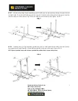
Page 3: ...t 8 to Short Support Base Assembly tube using M16 Bolt and M16 Locknut parts 9 12 and using 5 8 Pin and Clip parts 10 11 for extra safety See FIG 3 FIG 3 STEP 4 Assemble the extension frame Repeat ste...

Page 4: ...Base using 5 16 knob 2 5 16 flat washer 5 16 spring washer 5 16 hexagon bolt M10 Carriage Bolt and M10 Locknut parts 3 4 5 6 27 28 See FIG 5 FIG 5 STEP 6 Insert the Long Support Base part 1 into the...

Page 5: ...g up and the loop end of cradle should be facing outward and upward Insert the cradles in sequence as shown below in Fig 7 After all 4 cradles are on the Horizontal Arms tighten See FIG 7 FIG 7 STEP 8...

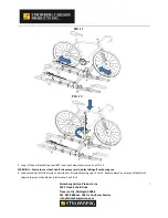
Page 6: ...tubes 1 Load inner bicycle first Loosen the 5 16 knob and expose the head of the 5 16 hexagon bolt outside the support base assembly then rotate vertical tube down See Fig 10 2 Load bicycle into Whee...

Page 7: ...FIG 12 5 Loop 1 Wheel Cradle Strap part 25 over each wheel and secure See FIG 13 WARNING Failure to use wheel cradle straps may result in bike falling off rack during use 6 Load second third forth bic...

Page 8: ...the wheel cradle when operating the tilt down feature For access to the rear of vehicle remove5 8 Pin and allow the rack to tilt downward For safety be sure to securely hold the bike rack while the p...

Page 9: ...raverse City Michigan 49686 231 947 8600 ext 108 for Customer Service info strombergcarlson com 9 Folded when not in use Feature Fold Vertical Arm to the horizontal position and then fold the Folding...

Page 10: ...mbly 4 3 5 16 Knob 6 18 Right Cradle Assembly 4 4 5 16 Flat Washer 12 19 Long J Hook Assembly 2 5 5 16 Spring Washer 6 20 Short J Hook Assembly 2 6 5 16 Hexagon Bolt 6 21 Eyebolt 2 7 Vertical Arm 2 22...

Reviews: