OPERATOR ADJUSTMENTS
THE FINE ADJUSTMENTS necessary to project the steadiest picture are made at the factory
by skilled technicians prior to shipping. In time, these adjustments will change, and require the attention of the
operator. Because of the advanced design of the Pro-35, these periodic asjustments can be made in a short time
with a minimum of effort.
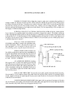
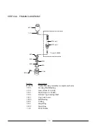
PAD ROLLER ASSEMBLIES
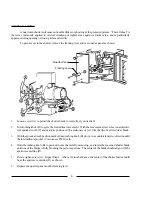
1. Place the pad roller assembly in the CLOSED position. Loosen set screw (A).
2. Loosen set screw (B) on the rear eccentric roller (C). Rotate pad roller (C)
away
from film sprocket (D).
3. Wrap TWO ticknesses of film around film sprocket (D). This spacing will permit the safe passage of film
splices.
4. Position pad roller (E) so that it just touches the two thicknesses of film on film sprocket (D).
5. Tighten set screw (A).
6. Rotate the eccentric pad roller (C) so that it too just touches the film on sprocket (D).
7. Tighten set screw (C).
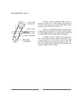
Lower (Holdback)
Sprocket Assembly
Pad Roller, Closed
(Open)
Upper (Feed)
Sprocket Assembly
Pad Roller, Closed
(Pad Roller,
Open)
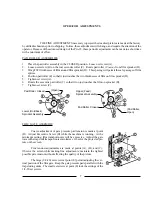
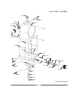
FILM GATE ASSEMBLY
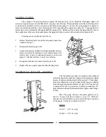
Coarse adjustment of gate pressure pad tension is made at point
(D). Adjust Ecccentric Screw (D) while the machine is running. At the
minimum setting, film transport noise will be excessive. Adjust the gate
toward the trap until transport noise minimizes. Observe the projected pic-
ture on the screen.
Fine tension adjustments are made at points (A), (B), and (C).
Observe the screen while making fine adjustments; maintain the lightest
possible gate tension without affecting the quality of the picture.
The large (1/4-20) set screws at point (E) permit adjusting the ver-
tical position of the film gate. Keep the gate pressure pads parallel with the
trap studio guides. The small set screws at point (E) lock the settings of the
1/4-20 set screws.
7
Summary of Contents for Ballantyne PRO-35
Page 15: ......


