BULB INSTALLATION (continued)
DISMOUNT THE UPPER COVER of the stainless steel bulb enclosure by removing the (2)
thumbscrews. Center the front bulb support pedestal by rotating the bulb focus knob adjacent to the douser
handle. Insert the bulb, with adapters mounted, into the lamphouse. Pass the cathode (-) end of the bulb through
the center hole in the rear of the reflector.
Take care not to dent or scratch the surface of the reflector.
Rest the
cathode end cap of the bulb in the
V
block behind the reflector, and mount the anode support casting to the anode
pedestal using the 71099 Bushing and 41-51107 Screw. Again, insert the bushing through the correct hole. Do
not overtighten the mounting screw; excessive torque may deform the 31245 casting.
RUN THE CATHODE LEAD through the insulated bushing at the back of the bulb enclosure
and connect it to the left (output) terminal post of the igniter. Connect the anode (+) lead to the rear terminal of
the shunt. Dress the anode lead close to the upright pedestal to minimize the shadow. Make certain all DC
connections are tight, and replace the stainless steel bulb enclosure cover.
REFER TO THE DOCUMENTATION packaged with the xenon bulb. It contains important
information prepared by the manufacturer of the bulb, including the recommended nominal current level at
which the bulb will begin operation. The current output adjustment for the X-90 power supply is located above
the ammeter. Do not exceed the maximum current level specified by the bulb manufacturer; the X-90 power
supply is capable of overdriving the xenon bulb.
STORE THE BULB PACKAGING and the warranty documentation in a secure location in the
projection booth. Record the installation date and lamphouse hours on the Bulb Record card on the back of the
console, or on the Xenon Bulb Record on the back cover of this manual.
TYPICAL CURRENT LEVELS
Wattage
Nominal Current
Do Not Exceed
1000
50 A.
58 A.
1600
65 A.
70 A.
2000
75 A.
90 A.
2500
90 A.
100 A.
X90/012
Summary of Contents for X-90
Page 2: ......
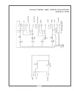
Page 21: ...X 90 LAMPHOUSE SCHEMATIC Analog Controls X90 019 ...
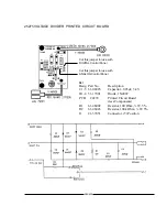
Page 23: ...ANALOG CONTROL PANEL PRINTED CIRCUIT BOARD Assembly No 23239 X90 021 ...
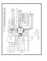
Page 24: ...X90 022 DIGITAL CONTROL PANEL PRINTED CIRCUIT BOARD Assembly No 23976 Wiring Diagram 1 of 3 ...
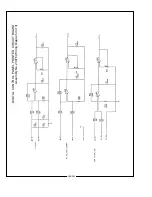
Page 25: ...X90 023 DIGITAL CONTROL PANEL PRINTED CIRCUIT BOARD Assembly No 23976 Wiring Diagram 2 of 3 ...
Page 26: ...X90 024 DIGITAL CONTROL PANEL PRINTED CIRCUIT BOARD Assembly No 23976 Wiring Diagram 3 of 3 ...
Page 43: ......
Page 44: ......


