BULB ALIGNMENT AND OPERATION
CLOSE AND LOCK the lamphouse access doors. Turn on the exhaust system. Close the
douser. Energize the distribution panel by turning the
MASTER
circuit breaker to the
ON
position (light ON).
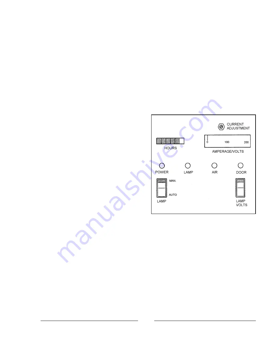
When the LAMP circuit breaker is closed, the indicator lights for
“POWER,” “AIR,”
and
“DOOR”
will light.
IN NORMAL MODE, the
LAMP “ON”
indicator and the xenon bulb will not light until cued
by the automation controller. For test purposes, select
“MAN.”
mode (upper position). The
LAMP “ON”
indicator will light, and the xenon bulb will ignite.
CHECK THE BULB CURRENT at the am-
meter. If not operating within specified range, adjust
the xenon power supply to obtain the correct output.
The operating current range is noted in the xenon bulb
warranty information. Do not exceed the maximum
current specified by the bulb manufacturer.
A NEW XENON BULB is normally operated
at or near its nominal current. As the bulb ages, the
quartz envelope normally will darken. The current can
then be gradually increased to compensate for the light
loss caused by the darkening envelope.
PRESS THE
“LAMP VOLTS”
switch to
change the ammeter to display arc voltage. To deter-
mine exact wattage, multiply volts time amperes.
THE ANALOG ELAPSED TIME METER (as illustrated) will record the hours of bulb
operation. The meter runs only when the xenon bulb is operating.
THE OPTIONAL DIGITAL INSTRUMENT PANEL continuously displays the bulb current
(A), arc voltage (V), wattage (W), and elapsed hours. Elapsed hours are displayed as Bulb Hours (BLB) and
Total Hours (HR). Bulb hours can be re-set to zero after replacing the xenon bulb. Prior to bulb ignition,
electrical data is displayed as zeros, but the backlighting of the display screen indicates that power is ON.
ADJUSTMENT CONTROLS are provided to correctly position and focus the xenon bulb.
Bulb adjustment controls, located on the distribution panel immediately above the
MASTER
circuit breaker,
position the bulb inside the reflector on the horizontal and vertical planes. The focus control knob, located
adjacent to the douser handle, moves the bulb in and out of the reflector on the horizontal plane.
REMOVE THE PROJECTION LENS, turn on the projector motor, and open the douser. A
black spot should appear in the center of the screen. Adjust, tilt, or reposition the console as required to center
the spot on the screen.
X90/013
Summary of Contents for X-90
Page 2: ......
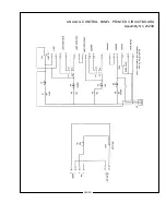
Page 21: ...X 90 LAMPHOUSE SCHEMATIC Analog Controls X90 019 ...
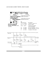
Page 23: ...ANALOG CONTROL PANEL PRINTED CIRCUIT BOARD Assembly No 23239 X90 021 ...
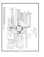
Page 24: ...X90 022 DIGITAL CONTROL PANEL PRINTED CIRCUIT BOARD Assembly No 23976 Wiring Diagram 1 of 3 ...
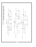
Page 25: ...X90 023 DIGITAL CONTROL PANEL PRINTED CIRCUIT BOARD Assembly No 23976 Wiring Diagram 2 of 3 ...
Page 26: ...X90 024 DIGITAL CONTROL PANEL PRINTED CIRCUIT BOARD Assembly No 23976 Wiring Diagram 3 of 3 ...
Page 43: ......
Page 44: ......


