A SCISSORS JACK is mounted to the rear of the console base to permit setting the projection
angle. To adjust, open the rear access door and loosen the (2) lock nuts on the inside of the upright frame. Tilt
the console to the desired projection angle by operating the jack with a 3/4 inch socket or box end wrench. When
set to the correct angle, retighten the lock nuts.
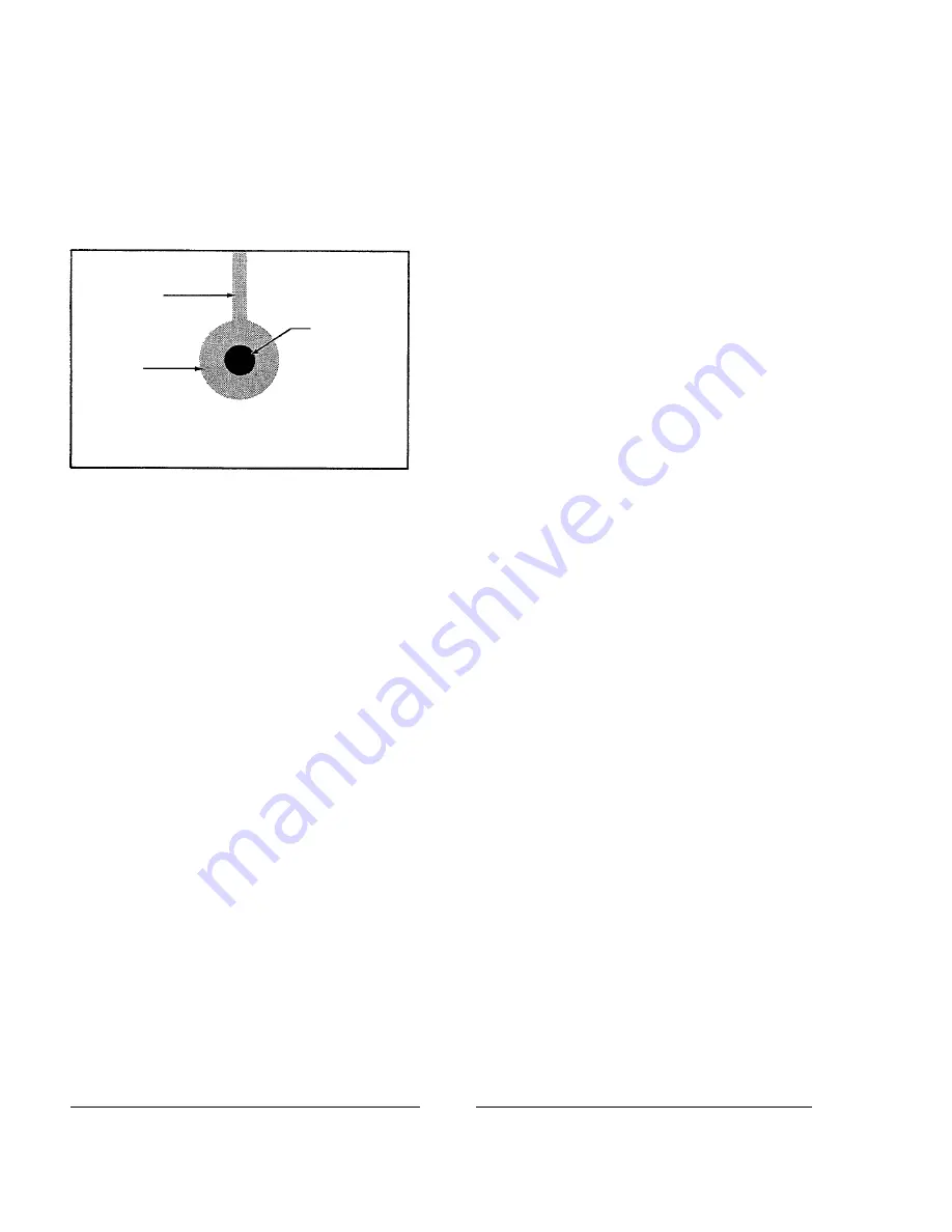
AN IMAGE similar to that illustrated on the
left should appear on the screen. Adjust the focus control
knob to sharpen and define the spot inside the shaded pro-
jection of the reflector center hole. Using a flat bladed
screwdriver, rotate the
VERT
and
HORIZ
adjustments until
the black spot is centered in the shadow as illustrated.
IF THE SHADOW of the bulb anode cable
is pronounced, shut off the lamp, allow the bulb to cool,
and open the access door. Dress the anode cable closer to
the bulb support pedestal.
THE SPLIT CATHODE
V
block behind the reflector is factory set to accommodate the 1.25"
(35mm) diameter of a standard 2000 watt bulb end cap. Operate the focus control knob adjacent to the douser
handle and observe the anode shadow as it moves inside the reflector center hole. The dark spot should remain
centered inside the shaded area. If the anode shadow raises or lowers as the bulb tracks forward or back, the
split cathode
V
block must be adjusted.
SLIDING THE SEGMENTS together or apart will raise or lower the center of the
V
. Each
segment mounts to the base using a single socket head screw; moving the segments equal distances will maintain
the optical center. The one-piece cathode support 71675 used with 2500 watt and 2000 watt “HS” bulbs should
require no such adjustment.
WHEN THE ANODE SHADOW is centered in the reflector center hole, insert the CinemaScope
aperture plate into the projector and install the projection lens. Adjust the focus control knob until the light field
on the screen is uniform. Close the lamphouse douser
frequently
during this operation to allow the lens to cool.
Prolonged lamphouse operation without film will damage the projection lens. After a uniform field is achieved,
file aperture plates to fit the screen and masking.
ALLOW THE BLOWER AND EXHAUST SYSTEM to operate for (10) minutes after extin-
guishing the bulb. This measure will prolong bulb life, and is required by the bulb manufacturer.
DAILY OPERATION
1. Turn all circuit breakers ON; close the lamphouse douser. Turn on the exhaust system (if not wired through
the console distribution panel). Place the
LAMP
switch in the
ON
position to ignite the xenon bulb. Open
the lamphouse douser only after the projector is running. DO NOT operate the xenon bulb for over twenty
(20) minutes with the lamphouse douser closed.
Support Pedestal
Shadow
Reflector
Hole
Anode
Shadow
PROJECTED IMAGE (without Lens)
X90/014
Summary of Contents for X-90
Page 2: ......
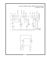
Page 21: ...X 90 LAMPHOUSE SCHEMATIC Analog Controls X90 019 ...
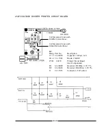
Page 23: ...ANALOG CONTROL PANEL PRINTED CIRCUIT BOARD Assembly No 23239 X90 021 ...
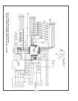
Page 24: ...X90 022 DIGITAL CONTROL PANEL PRINTED CIRCUIT BOARD Assembly No 23976 Wiring Diagram 1 of 3 ...
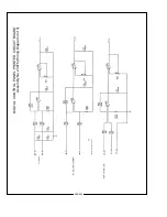
Page 25: ...X90 023 DIGITAL CONTROL PANEL PRINTED CIRCUIT BOARD Assembly No 23976 Wiring Diagram 2 of 3 ...
Page 26: ...X90 024 DIGITAL CONTROL PANEL PRINTED CIRCUIT BOARD Assembly No 23976 Wiring Diagram 3 of 3 ...
Page 43: ......
Page 44: ......


