DIGITAL DISPLAY
UPON ENERGIZING the LAMP circuit, the backlighting will illuminate the LCD screen.
When all blowers are operating and all access doors are closed and correctly secured, the display will appear as shown:
000V 000A 0000W
1234BLB 12345HR *
FOR PURPOSES OF ILLUSTRATION, the above display indicates a non-operating bulb
with 1,234 hours of use installed into a console with 12,345 hours of operation. The asterisk (*) at the end of the
second line, when flashing, indicates that the display is active and awaiting input. Upon bulb ignition, the upper
line will display the arc voltage (V), the DC current (A), and the operating wattage (W) of the bulb; the asterisk
symbol will be replaced by a plus (+) sign. The figures will shift for the first few moments of xenon bulb
operation, but will stabilize after the bulb reaches operating temperature and pressure.
IN THE EVENT of an open interlock switch, the lower line will display an appropriate diagnos-
tic measure, i.e. CHECK REAR DOOR or CHECK BLOWER. Diagnostic messages are defined as follows:
CHECK REAR DOOR:
Make certain the rear console access door is closed and locked.
CHECK FRONT DOOR:
Make certain the operator’s lamphouse access door and locked.
CHECK BLOWER:
Make certain the squirrelcage blower below the igniter is energized and operating,
and that the ducting to the bulb compartment is secure.
THE OPTIONAL 31902 EXHAUST AIR VANE SWITCH, if used, is wired in series with the
air flow switch mounted to the base plate below the reflector. Check both switches in the event of a CHECK
BLOWER error message.
WHEN THE INTERLOCK CIRCUIT is complete, closure of the LAMP switch, or the auto-
mation closure (3 & 6), will energize the contactor of the xenon power supply. The high open circuit (“no load”)
DC voltage will be displayed. When the open circuit voltage reaches 140 V.DC, the igniter will generate a RF
pulse to bridge the gap between the bulb electrodes. This pulse, coupled with the high open circuit DC voltage,
will ignite the bulb. The voltage reading will then fall to the bulb’s sustaining level, and the DC amperes (A) and
wattage (W) will be displayed continuously until the bulb is extinguished.
FAILURE of the xenon power supply to generate the high open circuit voltage will not cause an
error message to appear, but will be apparent by the
zero
voltage and current reading displayed on the LCD
screen. Make certain the (2) circuit breakers on the power supply cabinet are ON and not tripped, and check the
line fuse. These components are accessible through the off-operator side door of the X-90.
X90/016
Summary of Contents for X-90
Page 2: ......
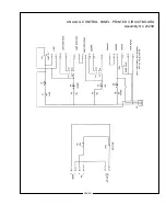
Page 21: ...X 90 LAMPHOUSE SCHEMATIC Analog Controls X90 019 ...
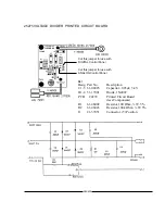
Page 23: ...ANALOG CONTROL PANEL PRINTED CIRCUIT BOARD Assembly No 23239 X90 021 ...
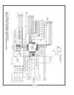
Page 24: ...X90 022 DIGITAL CONTROL PANEL PRINTED CIRCUIT BOARD Assembly No 23976 Wiring Diagram 1 of 3 ...
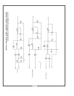
Page 25: ...X90 023 DIGITAL CONTROL PANEL PRINTED CIRCUIT BOARD Assembly No 23976 Wiring Diagram 2 of 3 ...
Page 26: ...X90 024 DIGITAL CONTROL PANEL PRINTED CIRCUIT BOARD Assembly No 23976 Wiring Diagram 3 of 3 ...
Page 43: ......
Page 44: ......


