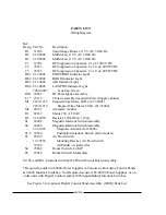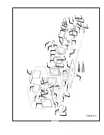
PARTS LIST
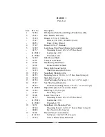
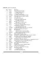
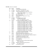
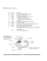
Wiring Diagram
Ref.
Desig. Part No.
Description
B1
31206
Squirrelcage Blower, 115 V.AC, 50/60 Hz.
B2
61-98002
Muffin Fan, 115 V.AC, 50/60 Hz.
B3
61-98002
Muffin Fan, 115 V.AC, 50/60 Hz.
C1
31909
RF Suppression Capacitor, .01 µf, 1000 V.DC
C2
76323
RF Suppression Capacitor, 2 x 1.0 µf, 600 WVDC
C3
76323
RF Suppression Capacitor, 2 x 1.0 µf, 600 WVDC
DS1 81-30002
POWER ON Indicator Light
DS2 81-30002
DOOR Indicator Light
DS3 81-30002
AIR Indicator Light
DS4 81-30002
LAMP ON Indicator Light
-
7056-0007
Lens Cap, Green
IGN 39862
DC Pulse Igniter Assembly
L1 * 25112
Choke Assembly (located in Power Supply cabinet)
M1 2479-1216
Elapsed Time Meter, 60 Hz. (81-32001)
-
2479-1214
Elapsed Time Meter, 50 Hz. (81-32004)
M2 40191
Ammeter, 0-200 A.
R1
82167
Shunt, 150 A. 50 mV.
R2
21-46059
Resistor, 150k Ohm, ½ Watt
S1
24406
Magnetic Interlock Switch Assembly
S2
24406
Magnetic Interlock Switch Assembly
-
21-61007
Magnetic Actuator (for 24406)
S1,2 39260
Pushbutton Interlock Switch (Euro models)
S3
85109
Air Flow Switch
-
12-30538
Mounting Bracket, Air Flow Switch
-
39188
Air Paddle, Actuator Arm
S4
23869
Rocker Switch, LAMP
S5
23868
Rocker Switch, Momentary
S4, S5, and DS1-4 included with 24236 Printed Circuit Board Assembly.
* Required on older 62-80000 Power Supplies in Consoles with Analog Control Panels
& 24406 Interlock Switches. Not Required on newer 62-80100 Power Supplies, or on
older units with Digital Controls and/or 39260 (pushbutton) Interlock Switches.
See Figure 3 for optional Digital Control Panel Assembly (24088) Parts List.
X90/020
Summary of Contents for X-90
Page 2: ......
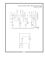
Page 21: ...X 90 LAMPHOUSE SCHEMATIC Analog Controls X90 019 ...
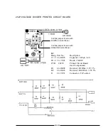
Page 23: ...ANALOG CONTROL PANEL PRINTED CIRCUIT BOARD Assembly No 23239 X90 021 ...
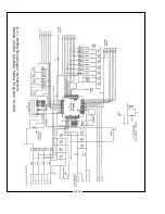
Page 24: ...X90 022 DIGITAL CONTROL PANEL PRINTED CIRCUIT BOARD Assembly No 23976 Wiring Diagram 1 of 3 ...
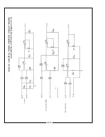
Page 25: ...X90 023 DIGITAL CONTROL PANEL PRINTED CIRCUIT BOARD Assembly No 23976 Wiring Diagram 2 of 3 ...
Page 26: ...X90 024 DIGITAL CONTROL PANEL PRINTED CIRCUIT BOARD Assembly No 23976 Wiring Diagram 3 of 3 ...
Page 43: ......
Page 44: ......


