INSTALLATION
(continued)
OBSERVING ALL SAFETY PROCEDURES, install a xenon bulb of the desired
wattage into the lamphouse. Check the bulb manufacturers documentation to determine the recom-
mended current range of the bulb. A new bulb is normally first operated at nominal current, which
is around 85% of the maximum level. DO NOT, at any time, exceed the maximum current level
specified by the bulb manufacturer.
IGNITE THE XENON BULB and check the current as indicated on the lamphouse
ammeter. Allow (30) seconds for the current to stabilize and provide an accurate reading. If the
current is not within the desired range, extinguish the bulb. It will be necessary to increase or de-
crease the DC output.
WARNING
Turn off ALL primary AC power before making any
adjustments or performing service procedures. Allow
several minutes for the capacitors to drain stored en-
ergy. The power supply normally operates warm to hot;
allow the unit to cool to room temperature.
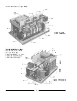
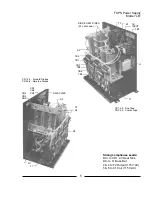
OUTPUT CURRENT ADJUSTMENT
Fine adjustment
of the DC current is made to the
NUMBERED
taps found on the upper three
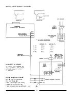
terminal blocks (TB4, TB5, TB6). Fine taps are numbered 1-2-3-4, with 1 providing the
lowest
output, increasing to 4, yielding the
highest
output. A fine tap adjustment raises or lowers the
current approximately four amperes. The three fine tap terminal blocks are interconnected by means
of a three-lead jumper wire assembly attached to like-numbered terminals.
To
increase
the DC output, move the jumper wire assembly to tap the next (3)
higher
numbered
terminals, for example, move from terminals 2 to terminals 3. ALL TAPS MUST BE ON THE
SAME NUMBERED POSITION (1-1-1, 2-2-2, 3-3-3, or 4-4-4). If the DC output is still too low
when terminals 4 are interconnected, see the following instructions for adjusting
coarse
taps.
To
decrease
the DC output, move the jumper wire assembly to tap the next (3)
lower
numbered
terminals, for example, move from terminals 3 to terminals 2. ALL TAPS MUST BE ON THE
SAME NUMBERED POSITION (1-1-1, 2-2-2, 3-3-3, or 4-4-4). If the DC output is still too high
when terminals 1 are interconnected, see the following instructions for adjusting
coarse
taps.
Coarse adjustment
of the DC current is made to the
LETTERED
taps found on the lower three
terminal blocks (TB1, TB2, TB3). Coarse taps are lettered W-X-Y-Z, with W providing the
lowest
output, increasing to Z at the
highest
output. The coarse tap terminals connect to contactor termi-
nals T1, T2, and T3. The (3) contactor leads must connect to the same lettered step (W-W-W, etc.).
A coarse tap adjustment raises or lowers the current approximately twelve amperes.
2
Summary of Contents for XENON FXPS
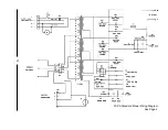
Page 12: ...FXPS Standard Model Wiring Diagram See Page 4 10 ...
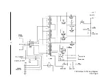
Page 13: ...FXPS Model LB Wiring Diagram See Page 5 11 ...
Page 18: ......


