background image

6

PART 1 • English

3.3 Step 3: Connecting the Antenna and the Set top box

Once you have installed the antenna in an open loop space and mounted the way you want it to be the 
next step is to connect it all together.
In order to be able to watch your favourite satellite programs, you need to connect your satellite antenna 
to a receiver by a cable.
The cable between the antenna and the Satellite receiver should not exceed 30m as it will decrease the 
quality of the signal
The use of a long or bad quality cable and not isolated jacks can cause a loss of the signal level, it would be 
preferable to use an RG6 Coaxial cable (HF 17VATC or 19VATC cable), in order to minimise a signal loss.

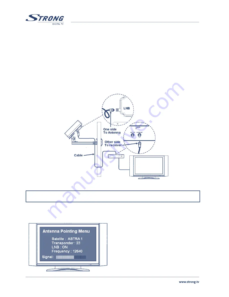
How to connect the cable to the antenna and the set top box?

It is important that the coaxial cable does not become damaged or kinked during the installation procedure.

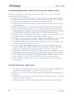
3.4 Step 4: Pointing and locating the Signal (first without Attenuation Thin Pad) 

Once all installed and connected, you can start 
adjusting your antenna in order to receive a signal. 
For that, you will need to move your antenna in 
three different ways in order to receive the maximum 
signal level & best reception quality. Whatever your 
choice of mount type, you will be able to adjust your 
antenna easily by following these instructions.

Summary of Contents for SlimSat SA60

Page 1: ...Satellite Antenna with integrated LNB SlimSat SA60 User Manual Picture similar...

Page 2: ...Step 3 Connecting the Antenna and the Set top box 6 3 4 Step 4 Pointing and locating the Signal rst without Attenuation Thin Pad 6 3 5 Optimum Pointing Finding the Signal with Attenuation Thin Pad 9...

Page 3: ...gerous and void the warranty n Any obstacle buildings trees etc will block the reception of the signal from the satellite to the antenna n Do not paint or add any substance on the antenna cover this w...

Page 4: ...satellite Note please take reference to the table of the Azimuth angles speci ed in the back pages of this manual Note To ensure an accurate compass reading stay away from large metal objects speci c...

Page 5: ...h Good Quality Signal Reception 3 2 Step 2 Installation Choice Depending on the choice of installation position for the SlimSat SA60 you can then decide on the mounting type all parts are included A T...

Page 6: ...5 PART 1 English English B Wall Mounting Type C Clamp on Balcony Type...

Page 7: ...use a loss of the signal level it would be preferable to use an RG6 Coaxial cable HF 17VATC or 19VATC cable in order to minimise a signal loss How to connect the cable to the antenna and the set top b...

Page 8: ...back of the antenna bracket Once achieved tighten both screws connecting the Skew Bracket B1 to the Antenna Body A1 B Elevation Angle Then obtain the Elevation angle according to the area location of...

Page 9: ...or to the left in order to receive the highest signal level from the satellite You should be able to nd the satellite signal rst and then the signal peak indicated on your screen Once you sweep throu...

Page 10: ...3 4 Step 4 Please af x Attenuation Thin Pad back onto the face of antenna cover and you may start repeating to make adjustment of Skew angle Azimuth and Elevation as done the same in chapter 3 4 Step...

Page 11: ...cable with a copper coated steel center conductor n Standard RG 59 cable cases too much DC drop and signal drop it can not be used to pass the satellite signal RG 6 coaxial cable must be used n Some a...

Page 12: ...rwise your antenna and receiver may not work properly and be subject to frequent outages in adverse weather Contact a professional concerning such intallations 7 0 TECHNICAL SPECIFICATION Input Satell...

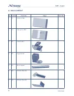
Page 13: ...English A 1 BOX CONTENT No Symbol Part name Image Quantity 1 A1 Antenna Body 1 2 P1 Attenuation PAD 1 3 B1 Skew Bracket 1 4 B2 Angle Bracket 1 5 B3 Main Support 1 6 B4 Window Bracket A 1 7 B5 Window B...

Page 14: ...1 Compass 1 12 S1 Screw M4x10 SEMS2 1 13 S2 Hex Bolt M6x12 SEMS2 1 14 S3 Hex Bolt M6x20 SEMS2 1 15 S4 Hex Bolt M6x45 SEMS2 1 16 S5 Round Head Square Neck Bolt M6x30 1 17 S6 Round Head Square Neck Bolt...

Page 15: ...1 A 2 APPENDIX 1 Great Britain...

Page 16: ...2 Germany...

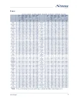
Page 17: ...3 France...

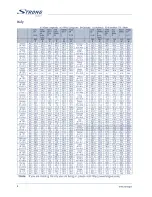
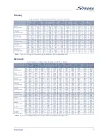
Page 18: ...4 Italy...

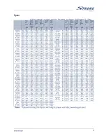
Page 19: ...5 Spain...

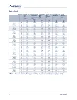
Page 20: ...6 Switzerland...

Page 21: ...7 Norway Denmark...

Page 22: ...8 Austria...

Page 23: ...9...

Page 24: ...10...

Page 25: ...rea User of this service will be free to you Within the scope of the European legislation on Waste Electrical and Electronic Equipment Directive 2002 96 EC valid as of August 2005 STRONG provides a re...

Reviews: