background image

Installation Manual

pg.7

www.snapav.com Support: 866.838.5052

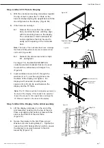
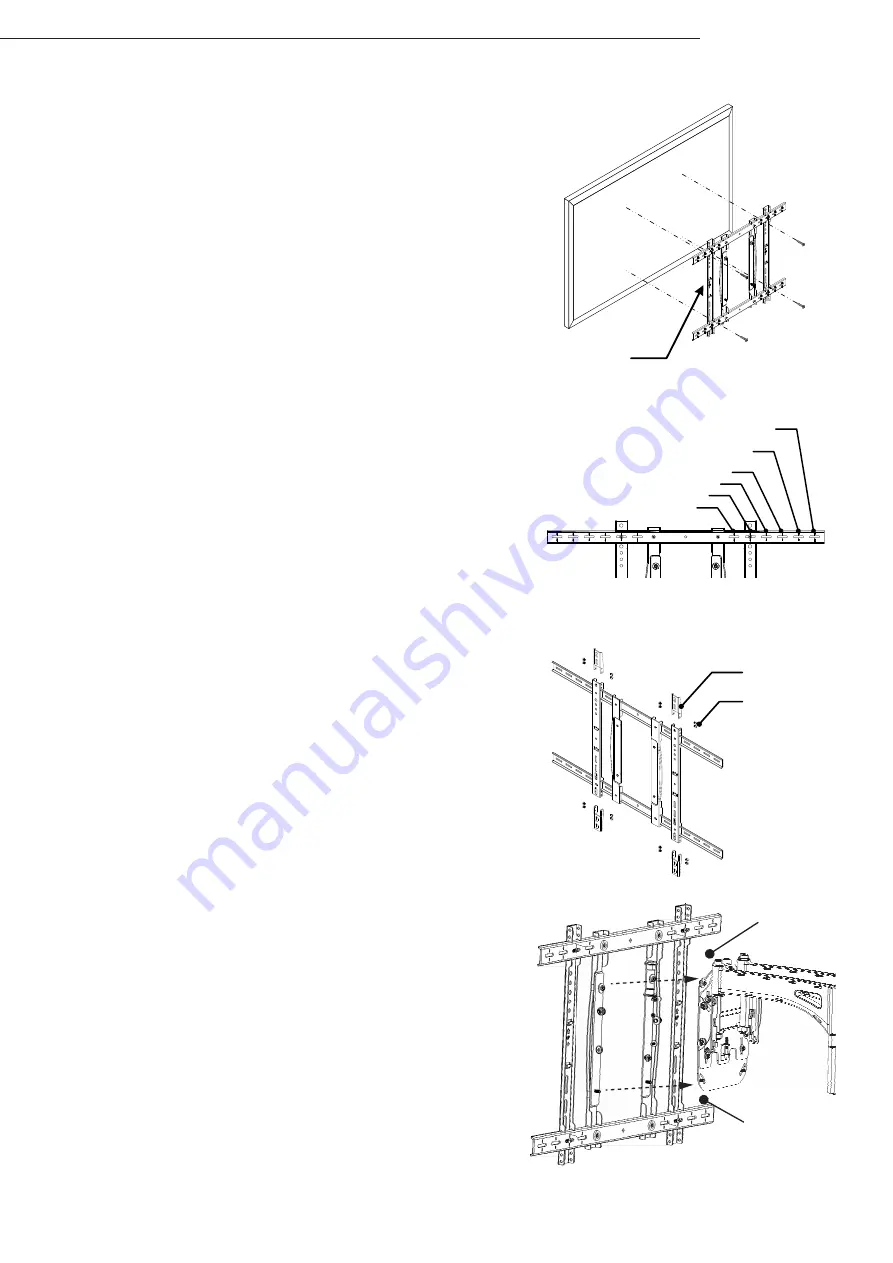
Step 4. Attach TV Plate to Display

A.  With the orientation marking (Up Arrow) towards 

the top of the TV, place the TV Plate on the 
back of display aligning the upright bars with the 
mounting holes on the display.  (Figure 8A)

B.  If the holes do not align:


B-1.   Remove the screws from the vertical 

bars, and slide the bars until they align 
with the mounting holes on the display.  
The vertical bars contain indicators for 
common patterns that can be used to 
easily set the spacing of the horizontal 
bars.


Note: 

The back of the horizontal bars have markings 

that follow VESA pattern horizontal increments from 
300 to 800. (Figure 8B)


B-2.   Reinsert the screws removed in step 4 

B-1, and tighten.


For larger TVs, the SM-RAZOR-ART2-XL 
contains extension brackets that can be used  
to extend the vertical bars to fit larger TVs.   
(Figure 9)

C.  Insert suitable screws (A to P) through the 

washers (S or T), and the upright bars into  
the back of the display, and tighten.  For 
displays with recessed mounting holes,  
spacers (Q or R) can be used between the 
display and the TV Plate.

Step 5. Attach the Display to the Arm Assembly

A.  Lift the display and place it on the end of the 

Arm Assembly hooking it to the top of the Arm 

Plate, and aligning the bottom screws with the 

slots on the bottom of the Arm Plate.   

(Figure 10)

B.  Secure the display to the Arm Plate using 2 

Washers (X) and Locking Nuts (Y).  Tighten the 

nuts with an S10 Socket Wrench (AD) to ensure 

the display is securely fastened to the Arm 

Assembly. (Figure 10)

Note: 

The TV Plate should be horizontally centered on 

the back of the display. If this needs to be adjusted, 
loosen the screws for the upright bars and align the 
TV Plate as needed on the back of the display.

Figure 8A

Orientation Marking

(Up Arrow)

Horizontal VESA Markings

300

400

500

600

700

(XL Only)

800

(XL Only)

Figure 8B

Figure 9

Extension Bracket (AF)

Extension Bracket

Screws (AG)

Step 5A

Step 5B

Figure 10

Summary of Contents for SM-RAZOR-ART2-L

Page 1: ...SM RAZOR ART2 L SM RAZOR ART2 XL Strong Razor Series Articulating Mount for Large and Extra Large Displays INSTALLATION MANUAL...

Page 2: ...pg 2 Installation Manual 2015 Strong...

Page 3: ...lbs SM RAZOR ART2 XL 100 lbs SM RAZOR ART2 L Up to VESA 600mm x 400mm SM RAZOR ART2 XL Up to VESA 800mm x 600mm Note Max VESA 800x600 requires use of AF Extension Brackets Tools Required Power Drill...

Page 4: ...drive machine screw M5x30 4 H Black Philips drive machine screw M5x40 4 I Black Philips drive machine screw M6x10 4 J Black Philips drive machine screw M6x20 4 K Black Philips drive machine screw M6x3...

Page 5: ...chors W and tap in with hammer if necessary Figures 1 2 B For Mounting on a Concrete Wall WARNING When installing wall bracket on cinder block Verify first that you have a minimum of 1 3 8 of concrete...

Page 6: ...Wall Plate D Secure the top of the Arm Assembly by tightening the 2 round Head Hex Screws using the S4 Allen Key AB Figure 6 E Secure the bottom of the Arm Assembly by placing the Bottom Mounting Bloc...

Page 7: ...e 9 C Insert suitable screws A to P through the washers S or T and the upright bars into the back of the display and tighten For displays with recessed mounting holes spacers Q or R can be used betwee...

Page 8: ...he display can be adjusted 5 from the pre adjusted center by tightening or loosening the Vertical Adjustment Screw located on the Arm Plate A Extend the Arm to access the Vertical Position Adjustment...

Page 9: ...the Latching Clip F Adjust the position of the Clip up or down so that the bottom lines up with the Latch Figure 15 B G Tighten the screws and retract the arm until a click sound is heard Repeat step...

Page 10: ...routed on the top or bottom of the arms and secured using zip ties Figure 17 Additionally wires can be zip tied to the clips on the vertical bars of the TV bracket Figure 18 Figure 18 Wire Clips Secur...

Page 11: ...fective in material or workmanship under normal conditions of use This warranty shall not apply to products which have been abused modified or disassembled Products to be repaired under this warranty...

Page 12: ...2015 STRONG 150325 2207...

Reviews: