2.0 YOuR iP bOx
2.1 DefAuLT Pin: 1234
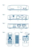
2.2 front Panel
Fig. 1
1.
status indicator:
Indicates status of ON or OFF modes.
2.
iR sensor:
Receives Standby/On signal from the remote control.
2.3 Rear Panel
Fig. 2
1.
AV
To connect your IP Box to an audio amplifier.
2.
LAn
To connect to your router with a RJ 45 network cable.
3.
HDMi
To connect your IP Box to your TV via HDMI cable.
4.
Power
To connect the included power adapter of 5 V.
2.4 side Panel
Fig. 3
1.
Micro sD card slot
To insert an optional Micro SD card.
2.
usb:
To connect USB devices like: mouse/keyboard/storage devices
2.5 Remote control
Fig. 4
1.
q
Turns the IP Box ON/Standby
2.
!
Turns the sound on or off.
3.
AsPecT
No function
4.
fAV
No function
5.
TV/RADiO
No function
6.
cOLOuR buTTOns
Different functions in menu mode
7.
Opens selection of wall papers
8.
Returns to the Android menu
9.
Returns to the previous menu or exits the App
10.
pq
Moves the highlight up/down in the menu
11.
tu
Navigates through the menus or changes values of settings in a
menu
12.
OK
Confirms a selection
13.
VOL+/VOL-
Increases/decreases the volume level
14.
PG+/PG-
Switches to the next/previous pages
15.
Switches to recently watched apps
16.
Turns the air mouse function ON or OFF.
17.
0-9
Numeric value input
18.
No function
19.
ePG
No function
5


