PART 1 • English
5
English
3.0 YOUR RECEIVER
3.1 Front Panel
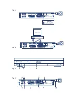
Fig. 5
1.
Mode indicator
The RED light indicates that the receiver is in STAND-BY mode. The GREEN light
indicates that the receiver is in AWAKE mode.
2.
Power ON/OFF
button
3.
Up/Down
buttons
4.
4 digits display
In STAND-BY mode indicates current time
In AWAKE mode indicates current channel number
3.2 Rear Panel
Fig. 6
1. ANT IN
To connect a terrestrial antenna for receiving broadcasting signal.
2. TO TV
To connect a TV set to receive analogue channels or to connect an extra receiver.
3. TV SCART Connector
To connect your receiver with your TV set using a SCART cable.
4. VCR SCART Connector
To connect your receiver with your VCR using a SCART cable.
5. AUDIO Right (Red RCA) and Left (White RCA)
These connectors give you the possibility to connect the audio signal to an external
amplifier or to the audio input of your TV.
6. VIDEO (YELLOW RCA)
This connector has a constant video signal for connection to TV set without SCART connector
or to VCR.
7. Coax S/PDIF (BLACK RCA)
To connect your receiver to digital audio amplifier
8. RS-232 Serial Port
Connect a PC to your receiver to download new software versions.
9. Main power switch
10 . Power Cord
Your receiver requires a current of 90 ~ 240 V AC (Auto-selectable), 50 ~ 60Hz ±5%. Make
sure to check the power specification before connecting your receiver to the wall outlet.
Summary of Contents for SRT 5011
Page 1: ...User Manual Digital Free To Air Terrestrial Receiver SRT 5011 Picture similar ...
Page 2: ......
Page 3: ......

