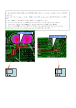
3. Check MAIN CLOCK 24MHz and SYSTEM CLOCK (PLL) to operate normally after SYSTEM
operates.
☞
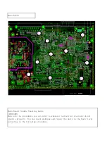
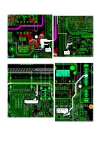
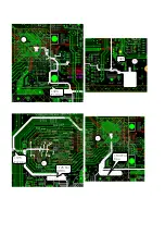
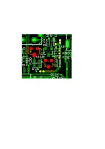
For the first thing, check 24MHz from Y401 flows into [OSCI(PIN B18)] of MAIN
CPU
If the 24MHz is unstable, Check Y401 is damaged or not.
If you are firm belief of damage for the device, then replace the device.
☞
And then, check that 800MHz is being supplied to DDR3 with RESET
If the clock 800MHz on Pin-J7&K7 of U401 is not generated from inside of the
chip,Please check the soldering state of U401,U402 and U403
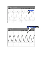
(MAIN CLOCK) 24MHz
(DDR3 CLOCK) 800MHz
Summary of Contents for SRT8500
Page 1: ...service manual DTT1609 ...
Page 5: ...1 5V 12V 5V For HDMI 6 3V3 For Tuner ...
Page 6: ...2 3V3 For Cpu 10 3V3 1V5 For Cpu 1V5 For DDR3 3 1V3 For Cpu 2 ...
Page 7: ...10 2V5 For DEMOD 5 1V3 For DEMOD 5V For USB 8 5V For Video Buffer 5V For Audio ...
Page 9: ...DDR3 CLOCK 800Mhz MAIN CLOCK ...
Page 13: ......
Page 16: ...Red signal input Blue signal input Green signal input ...
Page 19: ......
Page 20: ...2 SCHEMATIC COMPONENT LAYOUT AND BOM OF POWER SUPPLY 2 1 SCHEMATIC OF POWER SUPPLY ...
Page 33: ......
Page 34: ......
Page 35: ......
Page 36: ......


