THE VANES on the air flow switches should raise. With the MODE switch in the “MAN.”
position and the LAMP switch in the “ON” position, the running time meter should start and indicate elapsed
time. If this meter does not operate, check for continuity at the MODE and LAMP switches.
A DEFECTIVE RUNNING TIME METER will not prevent bulb ignition.
WITH THE “LAMP” SWITCH in the “ON” position, a distinct high voltage arc ping should
be heard at the spark gap in the igniter, and the flash of the xenon bulb should be visible through the ammeter as
a high DC voltage pulse is applied across the bulb electrodes.
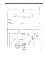
IF THE HIGH VOLTAGE PING or the flash at the ammeter is not apparent, check for 115
V.AC at terminals 5 & 6 at the terminal board. If 115 V.AC is present, and terminals are tight, check then the
“No Load” DC Voltage between the lamphouse and power supply. Remove either lead #5 or #6 at the terminal
board to prevent bulb ignition and defeat the door interlock switch. Check the DC voltage across terminals #10
(-) and #15 (+). A reading of 85 V.DC should be measured if using a high reactance power supply; 120-170
V.DC if using a switching type. If this voltage is not indicated, the problem is in the leads between the lamp-
house and power supply, or in the power supply boost circuit. See the trouble shooting section of the power
supply manual for additional instructions. Replace lead #5 or #6 at the igniter before proceeding.
THE SWITCHING-TYPE XENON POWER SUPPLY furnished with the spotlight system
includes thermal overload switches and protection circuits to prevent damage resulting from high or low input
voltage. Loss of DC open circuit voltage, or an interruption of DC sustaining current, may be traced to these
circuits. See the power supply manual.
IGNITER PRINTED CIRCUIT BOARD 40913 is required for use with the switching type
xenon power supply. If the lamphouse is equipped with an older type, replace it with the 40913 board. If the
lamphouse ignites only by means of the emergency ignition switch, replace the igniter PC board.
IF THE HIGH VOLTAGE ARC is audible at the lamphouse and the bulb does not flash, check
for a lamphouse DC lead arcing to ground. If no ground fault is detected, replace the bulb and attempt ignition
with the new bulb.
IF THE HIGH VOLTAGE ARC is audible at the lamphouse, the flash of the bulb is visible in
the ammeter, but ignition of the bulb is not sustained, the problem area is in the power supply. See the trouble
shooting section of the power supply manual for additional instructions.
IF THE HIGH VOLTAGE ARC is not audible or the flash of the bulb visible, the problem is in
the igniter or igniter PC board assembly.
EXCHANGE of components (i.e. igniters, printed circuit boards) between two similar Strong
Xenon Gladiators to aid in diagnosis of a problem is encouraged. This will not lead to equipment damage, and
will not void equipment warranty.
XG2/021
Summary of Contents for XENON GLADIATOR II
Page 2: ......
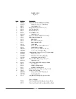
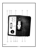
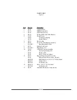
Page 27: ...1 2 3 4 5 6 7 8 9 10 11 12 13 FIGURE 1 XG2 025 ...
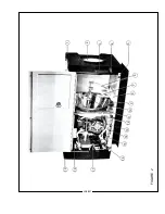
Page 29: ...1 2 3 4 5 6 7 8 9 10 11 12 13 14 15 16 17 18 19 FIGURE 2 XG2 027 ...
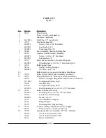
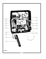
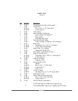
Page 32: ...1 2 3 4 5 6 7 8 9 10 11 12 13 FIGURE 3 XG2 030 ...
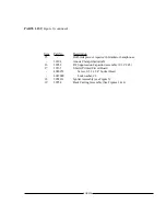
Page 34: ...1 2 3 4 5 6 7 8 9 10 11 12 13 14 15 FIGURE 4 XG2 032 ...
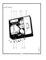
Page 36: ...1 2 3 4 5 6 7 8 9 10 FIGURE 5 IGNITER ASSEMBLY XG2 034 ...
Page 39: ...FIGURE 6 XG2 037 ...
Page 41: ...FIGURE 7 XG2 039 ...
Page 43: ...FIGURE 8 XG2 041 ...
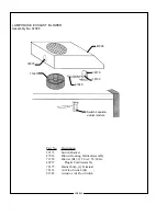
Page 46: ...58 59 FIGURE 9 Item 58 Bracket mounts to back surface of Item 31 XG2 044 ...
Page 50: ...FIGURE 10 47 XG2 048 ...
Page 53: ......
Page 54: ......


