Page 11 of 22
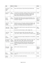
Item
Method
Criteria
Action
Contactor
Contacts
Visual
Contacts should be free of significant pitting or deterioration.
Replace
Pendant
(switches)
Function
Depressing and releasing push buttons should make and break
contacts in switch contact block and result in corresponding electrical
continuity or open circuit. Push buttons should be interlocked either
mechanically or electrically to prevent simultaneous energization of
circuits for opposing motions (example: up and down.)
Repair or
replace as
necessary
Pendant
(wiring)
Visual
Wire connections to switches in pendant should not be loose or
damaged.
Tighten or
repair
Pendant
(housing)
Visual
Pendant housing should be free of cracks and mating surfaces of
parts should seal without gaps.
Replace
Pendant
(cord)
Visual,
Electrical
Continuit
y
Surface of cord should be free from nicks, gouges, and abrasions.
Each conductor in cord should have 100% electrical continuity even
when cord is flexed back and forth. Pendant cord strain relief cable
should absorb the entire load associated with forces applied to the
pendant.
Replace
Table 1--2 Motor Brush Dimensions
Capacity (ton)
“B” Dimension (mm)
Discard
½ to 1
8
1 to 2
8
Summary of Contents for 72642
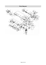
Page 16: ...Page 16 of 22 Parts Diagram ...


