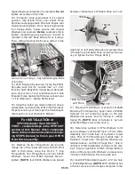
edge of the #1880 Grommet you will use later.
]
From “outside rear” slip one end of #1736 & #1737
Hoses into left Grommet and pass completely for-
ward connecting #1736 Hose to top #54 Fitting on
Cylinder and #1737 Hose to lower #54 Fitting...fin-
ger tighten both Hoses! Slip #1739 Edging on “left
forward” lower edge of “left” Body Wall to protect
hoses.
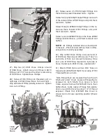
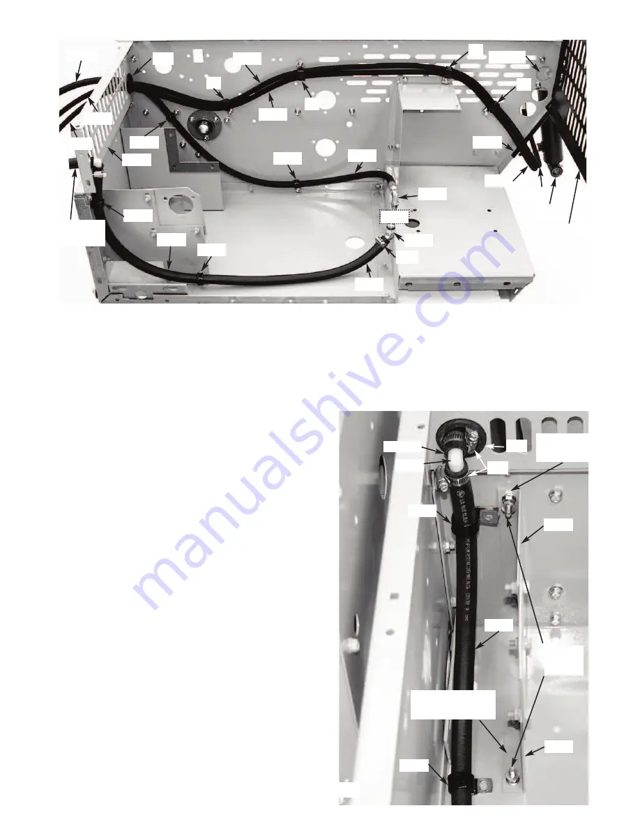
20) Using Photos as guide, loosely route both
Hoses ”front to rear” along left Body Wall. Insert
this “pair” of Hoses into a series of #69 Coated
Clips and orient them “up or down” at locations in-
dicated. Remove Nuts from Bolts that are to hold
Clips. Attach each Clip to its appropriate Bolt and
apply Nuts finger tight. Note how the Hoses are
stacked #1736 on top of #1737. Use care to follow
the hose path shown in the photo as it will elimi-
nate damage to other components.
[NOTE:
longer Bolts are provided if you feel original
ones are too short to work with.]
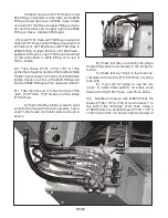
21) Remove the Flange Bolt from the “top rear
flange” of #1603 Right Support and the Carriage
Bolt from the “lower forward” flange of #1603 Right
Support. From “outside” the Body replace these
Bolts with 5/16” x 1-1/2” long Flange Bolts and se-
cure “inside” with Flange Nuts...tighten securely!
Screw a second Flange Nut [flange out] over
threads of each Bolt...allow 7/16” of thread to
show. [Check Photo for location and orientation of
the above bolts.]
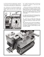
22) Assemble #1730 & #1728B Hoses together
with #1734 - 90 deg Elbow and two #931 Hose
Clamps...”center” each Clamp and tighten! From
“inside” Body slide remaining end of #1728B Hose
through #279 Grommet. Slip two #1905 Coated
Clips over remaining end of #1730 Hose.
With #931 Hose Clamp (of #1728B Hose) against
the “inside face” of #279 Grommet, align #1905
Location of:
1726
931
1730
1730
1727
1733
1736
1736
1737
1737
1733
1904
1737
1739
1736
2336
1610
1664A
1905
1728B
[2” long]
1905
1904
1645
279
69
69
69
69
931
1728B
1734
1905
1730
1603
1603
Flange
Bolts
1905
279 Top Rear
Flange
Lower Forward
Flange
1721
BM56


