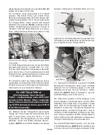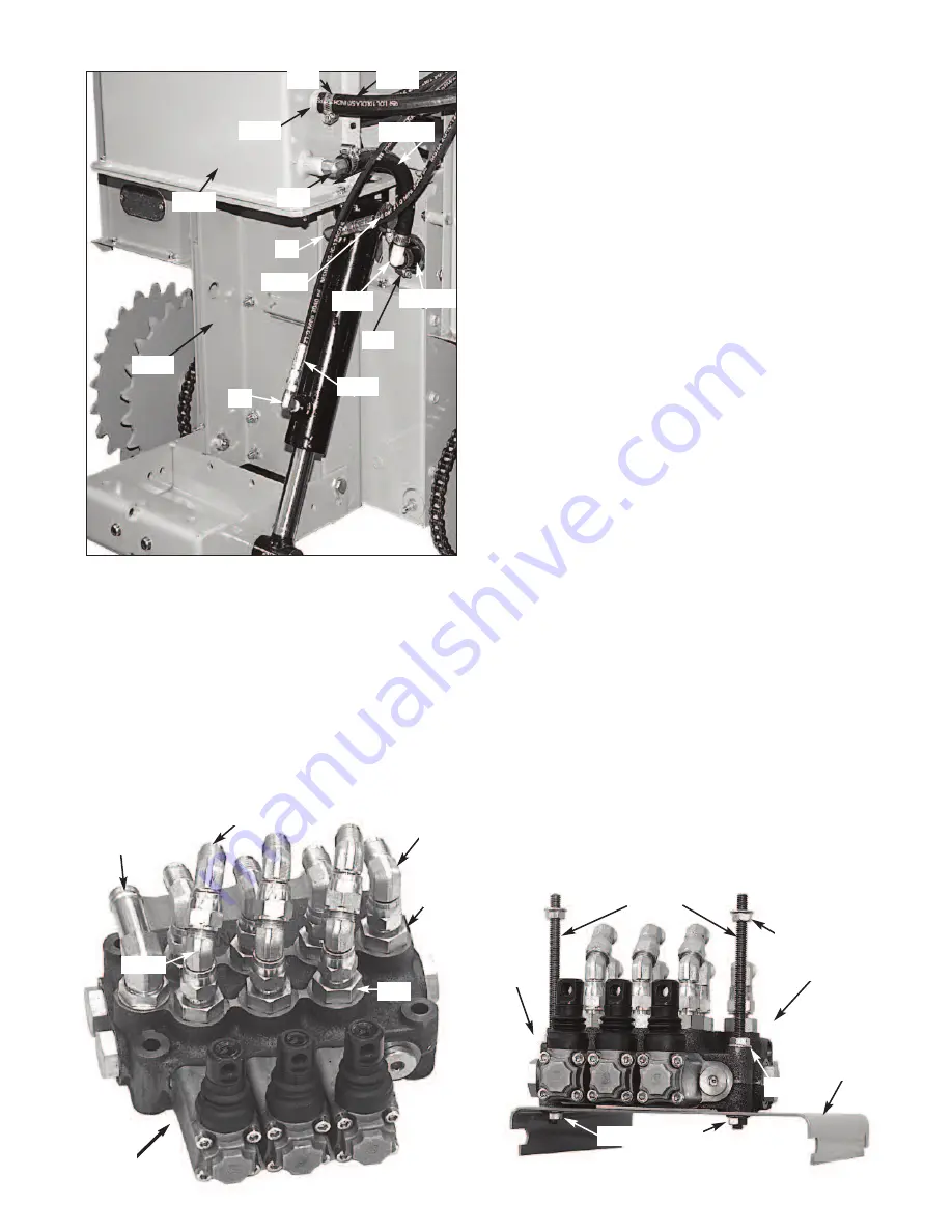
27) Slip two (2) #931 Hose clamps around
#1728A Hose. Attach one end of Hose to #619
Fitting on #1719 Tank and the other to remaining
#1734 Elbow... tighten Hose Clamps.
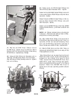
28) Screw #1738 Fitting into threaded port on
right side of #1920 Valve Bank. Turn until tight ...
stop with tube of Fitting pointing rearward... tighten
lock-nut on Fitting.
29) Screw seven (7) #790 Straight Fittings into
the remaining seven threaded holes... tighten.
Screw four (4) #676 Right Angle Fittings over each
of the
rearward
four #790 Fittings and point them
rearward... tighten.
Screw three (3) #2582 45 deg Fittings on the re-
maining three
forward
#790 Fittings and point
them rearward... tighten
Screw a second #2582 Fitting on the three #2582
Fittings installed above... point them rearward and
tighten.
NOTE:
All
Fittings installed
above
should point
to the rear... Photo at lower left has them in differ-
ent positions to clarify assembly!
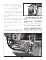
30) Slip a #931 Hose Clamp over each end of
#1729 Hose. Slip one end of Hose over “Tube” on
right side of Tank and connect remaining Hose
end onto #1729 Fitting mounted to right side of
Valve. Center each #931 Clamp ...tighten both!
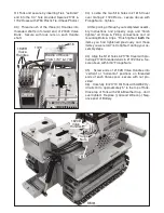
31) Mount #1920 Valve over two 5/16” holes on
forward end
of #1615 AR Right Cover using #1720
Threaded Rods as bolts.
Note Flange Nuts are mounted flush with each
Shaft end “under” Cover. A second Flange Nut is
screwed on both Shafts from above to hold
Valve...square Valve with #1615AR Cover, then
tighten Nuts. Lastly, apply a Flange Nut upside-
down on each Rod leaving about 1/2” of thread
exposed. Check that #1615AR Box Cover is
closed and in it’s new operating position! [Check
Photos]
931
Nut
Nut
1728A
1728B
54
1732
1734
1731
54
1729
Tube
1719
619
931
1680
Flange Nuts
1720
1615AR
1920
676
1738
790
790
2582
2582
Nut
[not
shown]
1920
Valve
Bank
BM58


