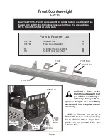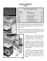
BM64
STEP 2.
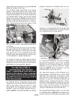
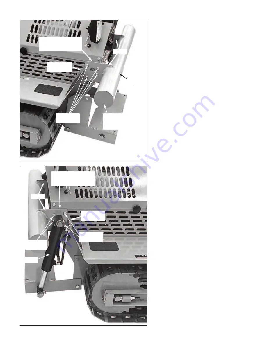
Raise the #1767 Counter-
weight into position such that the ”ears”
of the “bar” cradled the Right & Left Body
Walls.
STEP 3.
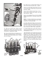
Insert a #1758 Spacer Plate
between each “ear” and its mating Right
or Left Body Wall. Align the four (4) 5/16
holes in each “ear” with 5/16 holes in its
respective Right or Left Body Wall and
5/16 holes in right and left ends of #1782
Grill... see Photos at left and lower left.
STEP 4.
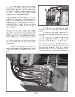
From
outside
, slip an R Bolt
into each aligned set of 5/16 holes... se-
cure inside Body & Grill with HH Nuts...
tighten all eight Bolts.
STEP 5.
Follow your PP35 Power
Pack Kit for remaining instructions for
proper instalation of the #2336 Cylinder,
Hoses, etc.
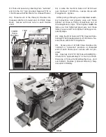
Finished assembly of a Hydraulic
Front Hitch Kit... see Photo at left.
“ears”
“ears”
“bar”
1767
Front
Counterweight
1758 Spacer Plate
between “ear” and
Right Body Wall.
1758 Spacer Plate
between “ear” and
Left Body Wall.
Right
Body Wall
Left
Body Wall
R Bolts &
HH Nuts
R Bolts &
HH Nuts
2336
R Bolts &
HH Nuts


