background image

INSTALLATION: ADJUSTING LEVELERS / WIRING DIAGRAMS / FIELD WIRING CONNECTIONS 

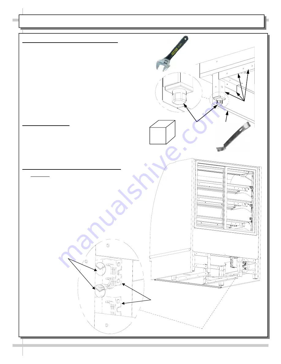
9. Cases With Levelers: Adjust Levelers 




After case is in position, adjust case so it is level 
and plumb (see illustration at right). 



You may need to remove front and/or rear      Toe
-Kick to access levelers. 



Use adjustable wrench (and possibly a pry bar)  
to adjust leveler.   



Do not use pry bar on toe-kick (it may buckle).




Do not use pry bar on end panel (it may chip).




Use pry bar ONLY on base frame to avoid     
damaging case.




Use block to reach base frames with pry bar. 



See illustrations at right.


10.  Wiring Diagram 




Each case has its own wiring diagram folded and 
in its own packet. 



Wiring diagram placement may vary; it may be 
placed near condenser fan cover, ballast box, 
raceway cover, or other related location.   


11.  Field Wiring Connections (HMG3953) 




Caution!  Wiring process must be performed by 
certified electricians only. 



Remove ballast box face (by removing screws). 



Remove screws from inner support.  



Knockouts are located on side and rear of box for 
making electrical connections. 



Several ballast locations (depending upon model) 
are shown in illustrations on this sheet.




Serial label (at case rear) lists voltage rating. 



See next page for field wiring connections to 
other models. 

Pry Bar 

Base 

Frame 

Leveler 

Adjustable 

Wrench 

Toe-Kick 

Block 

Ballasts 

Field wiring 

connection / 

junction box 

Summary of Contents for Harmony HMG2653

Page 1: ...FRIGERATED CASES 33 DEEP SERVICE NON REFRIGERATED HMG L 53 PLEASE NOTE THE FOLLOWING 1 YOUR SPECIFIC MODEL NUMBER IS ON THE SERIAL LABEL ON CASE REAR NEAR MAIN POWER SWITCH 2 SEE MODELS AND THEIR RESP...

Page 2: ...ITS CASTERS ADJUSTING FRONT TOE KICK INSTALLATION FIELD WIRING CONNECTIONS FOR VARIOUS MODELS INSTALLATION FRONT GLASS ALIGNMENT ADJUSTMENT INSTALLATION DISPLAY CASE START UP INSTALLATION RAISING THE...

Page 3: ...ensions Note 3 If your specific model is not found contact technical service phone number is listed at Technical Service section in this manual for dimensions Note 4 CDRs Customer Design Requests are...

Page 4: ...CE This equipment MUST be installed in compliance with all applicable NEC federal state and local electrical and plumbing codes CAUTION CAUTION Fluorescent lamps have been treated to resist breakage a...

Page 5: ...d Maintain support of case at all times or center of gravity may cause case to fall Unlock Casters Roll unit to rear of skid Ramp Roll down ramp and off from skid Support while rolling case down ramp...

Page 6: ...of the 5 to 8 bolts in a cross wise pattern Work your way around the pattern tightening more firmly at each pass Do not firmly tighten one bolt and then start on the next H After the cases are bolted...

Page 7: ...from slot empty and replace See cleaning schedule for specifics on cleaning D Collapsible Rear Ledge When not in use lift up and allow support rod to collapse Lower ledge downward Reverse this procedu...

Page 8: ...ram Each case has its own wiring diagram folded and in its own packet Wiring diagram placement may vary it may be placed near condenser fan cover ballast box raceway cover or other related location 11...

Page 9: ...trip PVC Wireway HMG2653R Only Ballasts 13 Field Wiring Connections HMG7553 Field wiring connection junction box is at case rear underside See illustration below Single phase leads are provided Option...

Page 10: ...compromise the environment inside the case and may create condensation Follow the five steps listed below to assure proper front glass alignment 2 Front to Back Leveling Place a level on top of case p...

Page 11: ...r See illustrations below All lights should come on at same time First Light Switch time lighting may require a short warm up period for the bulbs Slightly dim or a flickering of new bulbs is normal T...

Page 12: ...nal position See illustration below View of Rear Doors being lifted up pivoted out and away from case View of Curved Glass being raised 18 Removing the Rear Doors Note Optional Swinging Door are on HM...

Page 13: ...llation of lamp Align pins with slot Insert pins into socket by rotating the bulb 1 4 turn to secure either the upper or lower pinned contacts into the sockets Rotate the remaining bulb contacts 1 4 t...

Page 14: ...ations at right 2 Plug and Cord Positioning Plug is to connect to LED light at raceway side of case Before attaching LED light to case verify that plug connects to LED properly without cord doubling b...

Page 15: ...with a household or commercial cleaner X Vacuum under case to remove all dust and dirt that may collect under case Clean Case Interior X Glass shelves can be cleaned with a household or commercial gla...

Page 16: ...orm this task Confirm that unit has been field wired correctly Caution Only a certified electrician is to perform this task Case Lights Not Working Check that ALL lights are plugged in and or receptac...

Page 17: ...ions on contacting Structural Concepts Technical Service Department See images below for samples of both refrigerated and non refrigerated serial labels Sample Serial Label For Non Refrigerated Case S...

Page 18: ...defined herein suffered or incurred by SCC as a result of or in connection with any act omission or use of the Goods by Purchaser its employees or customers or any breach of this Agreement by Purchas...

Reviews: