Secotom-10
Instruction Manual
6
Lift the transparent cover to an angle of 45
0
-60
0
.
Lift the cooling fluid nozzles to gain access to the cut-off wheel
mounting.
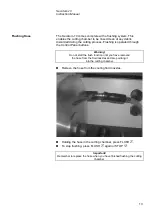
Insert the stop pin into the hole of the inner flange.
Use the fork spanner (17 mm) to loosen the flange screw.
Remove the outer flange.
Mounting the Cut-off Wheel
IMPORTANT
For manual cutting: only diamond or CBN cut-off wheels with a metal body
are allowed. Abrasive SiC or Al
2
O
3
cut-off wheels or saw blades may not be
used when the manual cutting table accessory is fitted to the Secotom-10.
IMPORTANT
The tolerance between the spindle and inner flange is very small which
means that the two surfaces must be absolutely clean.
Never try to squeeze the cut-off wheel on as this may damage the spindle
or the cut-off wheel. If there are any small burrs, remove them with grinding
paper (grit size 1200).
Outer flange
Flange screw
Hole for stop pin
Summary of Contents for Secotom-10
Page 1: ...Manual No 15037001 Date of Release 0 2010 Secotom 10 Instruction Manual...
Page 18: ...Secotom 10 Instruction Manual 14 2 Basic Operation Power Spindle speed 300 500 rpm Front Panel...
Page 49: ...Secotom 10 Gebrauchsanweisung Handbuch Nr 15037001 Auslieferungsdatum 1 0 2010...
Page 54: ......
Page 101: ...Secotom 10 Mode d emploi Mode d emploi no 15037001 Date de parution 1 0 2010...
Page 106: ......
Page 120: ...Secotom 10 Mode d emploi 14 2 Fonction de base Power Spindle speed 300 500 rpm Panneau frontal...
Page 151: ...Manual No 15037001 Date of Release 10 05 2010 Secotom 10 Spare Parts and Diagrams...
Page 158: ......
Page 159: ......
Page 160: ......
Page 161: ......
Page 162: ......
Page 163: ......
Page 164: ......
Page 165: ......
Page 166: ......
Page 168: ......
Page 169: ......
Page 171: ......
Page 172: ......
Page 173: ......


