Secotom-10
Instruction Manual
7
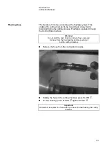
Mount the cut-off wheel (using the 22mm insert if necessary) and
remount the outer flange, with the machined face towards the
inner flange.
Insert the locking pin in the hole in the inner flange.
Gently fasten the flange screw using the fork spanner 17 mm.
Lower the cooling fluid nozzles to their operating positions.
The distance between the cut-off wheel spindle and the cutting table
can be adjusted to suit the individual cut-off wheels or wear caused
during the cutting process.
Use the control on the side of the Secotom-10 (illustrated in
“Getting Acquainted with the Secotom-10”) to raise and lower
cut-off wheel mounting.
IMPORTANT
When mounting cut-off wheels with a 12.7 mm centre hole, make sure that
the 22 mm arbour insert has been removed. Failure to do this will result in
the cut-off wheel being pressed out of shape.
Adjusting the Height of the
Cut-off Wheel
Inner flange
Hole for stop pin
12.7 mm
axle
Insert for wheels with
22 mm
arbour hole
Summary of Contents for Secotom-10
Page 1: ...Manual No 15037001 Date of Release 0 2010 Secotom 10 Instruction Manual...
Page 18: ...Secotom 10 Instruction Manual 14 2 Basic Operation Power Spindle speed 300 500 rpm Front Panel...
Page 49: ...Secotom 10 Gebrauchsanweisung Handbuch Nr 15037001 Auslieferungsdatum 1 0 2010...
Page 54: ......
Page 101: ...Secotom 10 Mode d emploi Mode d emploi no 15037001 Date de parution 1 0 2010...
Page 106: ......
Page 120: ...Secotom 10 Mode d emploi 14 2 Fonction de base Power Spindle speed 300 500 rpm Panneau frontal...
Page 151: ...Manual No 15037001 Date of Release 10 05 2010 Secotom 10 Spare Parts and Diagrams...
Page 158: ......
Page 159: ......
Page 160: ......
Page 161: ......
Page 162: ......
Page 163: ......
Page 164: ......
Page 165: ......
Page 166: ......
Page 168: ......
Page 169: ......
Page 171: ......
Page 172: ......
Page 173: ......


