background image

Electromagnetic Compatibility Tables

33

Like other electrical medical equipment, the 1088 Camera requires 

special precautions to ensure electromagnetic compatibility with other 
electrical medical devices. To ensure electromagnetic compatibility 
(EMC), the 1088 Camera must be installed and operated according to the 
EMC information provided in this manual. 

Note

The 1088 Camera has been designed and tested to comply 
with IEC 60601-1-2:2001 requirements for EMC with other 
devices.

Caution

Portable and mobile RF communications equipment may 
affect the normal function of the 1088 Camera.

Warning Do not use cables or accessories other than those 

provided with the 1088 Camera, as this may result in 
increased electromagnetic emissions or decreased 
immunity to such emissions.

Warning

If the 1088 Camera is used adjacent to or stacked with 
other equipment, observe and verify normal operation 
of the 1088 Camera in the configuration in which it will 
be used prior to using it in a surgical procedure. 
Consult the tables below for guidance in placing the 
1088 Camera.

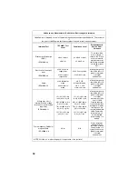
Guidance and Manufacturer's Declaration: Electromagnetic Emissions

1088 Camera is intended for use in the electromagnetic environment specified below. The customer 

or the user of 1088 Camera should ensure that it is used in such an environment.

Emissions test

Compliance 

Electromagnetic Environment - guidance

RF emissions CISPR

11

Group 1

1088 Camera uses RF energy only for its 

internal function; therefore, its RF emissions are 

very low and are not likely to cause any 

interference in nearby electronic equipment.

RF emissions CISPR

11

Class B

1088 Camera is suitable for use in all 

establishments, including domestic 

establishments and those directly connected to 

the public low-voltage power supply network 

that supplies buildings used for domestic 

purposes.

Harmonic emissions

IEC61000-3-2

Class A

Voltage Fluctuations/

flicker emissions

IEC61000-3-3

Complies

Electromagnetic Compatibility 

Summary of Contents for 1088

Page 1: ......

Page 2: ......

Page 3: ... Using the Console Controls 20 Powering On the Camera 20 Using the White Balance Switch 20 Using the Gain Button 21 Using the Enhance Up and Down Buttons 21 Selecting a Surgical Specialty 21 Using the Light Zoom Switch 21 Using the Shutter Switch 22 Using the NTSC PAL Switch 22 Controlling Remote Video Accessories 22 Using the Camera Head Buttons 23 Using the P Button 23 Using the W Button 24 Usin...

Page 4: ...7 Steris System 28 Sterrad System 28 Using Sterile Drapes 29 Maintaining the 1088 Camera 29 Replacing the Fuses 29 Periodic Maintenance Schedule 29 Disposing of the 1088 29 Troubleshooting 30 Electromagnetic Compatibility Tables 33 Technical Specifications 37 Warranty 39 Service and Claims 40 International Service 41 ...

Page 5: ...nce of hazardous voltage Refer all service to authorized personnel Warning To avoid potential serious injury to the user and patient and or damage to this device the user must 1 Read this operating manual thoroughly and be familiar with its contents prior to using this equipment 2 Carefully unpack the unit and check if any damage occurred during shipment If damage is detected please refer to the S...

Page 6: ...odifications and or repairs are carried out exclusively by Stryker Endoscopy The electrical installation of the relevant operating room complies with the applicable IEC CEC and NEC requirements Stryker Endoscopy reserves the right to make improvements to the product s described herein Product s therefore may not agree in detail to the published design or specifications All specifications are subje...

Page 7: ...ave specific meanings that clarify the proper use and storage of the 1088 Camera The following list defines the symbols associated with this product Operating humidity ratings Operating pressure ratings Operating temperature ratings Denotes compliance to CAN CSA C22 2 No 601 1 M90 and UL2601 1 Type BF applied part Equipotentiality Protective earth ground ...

Page 8: ...6 ...

Page 9: ... Console The camera console is the control center for the 1088 Medical Video Camera and processes the video and photographic images captured during the surgical procedure The front console panel features controls for adjusting the enhance gain and white balance and for selecting surgical specialty settings that optimize camera performance for specific surgical procedures The rear console panel pro...

Page 10: ...8 Figure 1a The 1088 Camera console front panel Figure 1b The 1088 Camera Console rear panel 1 2 5 6 7 3 4 8 9 10 11 12 13 14 15 16 17 18 19 20 21 22 23 ...

Page 11: ...he Sidne Console to enable voice operation 9 Ethernet Port Provides an ethernet connection for remote diagnoses and future software upgrades 10 RGB Out 11 S Video 1 Out 12 S Video 2 Out 13 Composite Out 14 AC Power Inlet 15 Equipotential Ground Plug 16 Light Zoom Switch Selects either the LIGHT or ZOOM function for the arrow buttons on the camera head 17 NTSC PAL Switch Selects NTSC or PAL video s...

Page 12: ...op of the camera head see the Operating the Camera Head section of this manual Figure 2 below lists the features of the camera head Figure 2 The 1088 HD Camera Head 1 Soaking Cap Protects the cable connector during cleaning and sterilization 2 Camera Head Captures photographic and video images provides camera controls and connects to a focusing coupler 3 Camera Cable 4 Cable Connector Connects the...

Page 13: ...es a focusing ring to adjust image sharpness The features of the coupler are listed in Figure 3 below Figure 3 The coupler 1 Camera End Threads onto the camera head 2 Focusing Ring Adjusts the coupler focus 3 Ventilation Port Provides ventilation for the coupler lens 4 Endobody Clamp Secures the scope to the coupler 5 Scope End Receives the endoscope 1 2 3 4 5 ...

Page 14: ...era involves three steps 1 Setting up the console 2 Setting up the camera head 3 Setting up the coupler Setting Up the Console Caution Portable and mobile RF communications equipment may affect the normal function of the 1088 Camera When choosing a location for the 1088 Camera consult the Electromagnetic Compatibility section of this manual to ensure proper function To set up the console make the ...

Page 15: ... connect the Sidne interface as well See Diagram 2 Warning When the 1088 Camera is used with other equipment leakage currents may be additive Ensure that all systems are installed according to the requirements of IEC 60601 1 1 Warning Do not touch the internal pin of the VIDEO OUT BNC jack and the patient simultaneously Output Type Output Cable Connector Analog RGB RGB 8 pin DIN push only connecto...

Page 16: ...14 Wiring Diagram 1 Camera Light Source and Flat Panel Monitor DVI I VGA Adapter Flat Panel Monitor 1088 Camera X7000 Light Source DVI BNC DVI ...

Page 17: ...ting Up the 1088 Camera 15 Wiring Diagram 2 Camera Light Source SDC Pro HD Sidne and Flat Panel Monitor 1088 Camera DVI Sidne StrykerVision 1 Monitor X7000 Light Source SDC HD DVI DVI Remote Remote BNC USB ...

Page 18: ...itional monitor may be connected using any open camera output 3 Power on the monitor 4 Power on the camera Note A color bar pattern will appear on the monitor when the camera head is not connected to the camera console Follow the instructions in the Setting Up the Camera Head section of this manual to connect the camera head to the console X7000 Light Source VGA 1088 Camera CRT Monitor StrykerVisi...

Page 19: ...h the red dot on the camera connector port on the front console panel see Figure 4 Push in the connector until it locks in place Figure 4 Connecting the camera head to the console Note To unplug the camera from the control unit grasp the knobbed portion of the connector and pull straight out This releases the connector latching mechanism Caution Do not severely bend the camera cable or damage may ...

Page 20: ...igure 5 Attaching a coupler to the camera head Caution Do not overtighten the coupler as this may damage the front window of the camera Note For direct coupled scopes scopes that require no coupler thread the endoscope directly into the camera head until it forms a tight seal Caution Do not overtighten a direct coupled scope as this may damage the front window of the camera ...

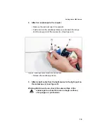
Page 21: ...ope into the scope end of the coupler b See Figure 6 Figure 6 Attaching an endoscope to the camera head Release the endobody clamp 3 Attach a light cable from the light source to the light post on the endoscope c see Figure 6 Warning Before each use check the outer surface of the endoscope to ensure there are no rough surfaces sharp edges or protrusions a b c ...

Page 22: ...nce procedure before every surgical procedure Note Ensure a scope and light source are attached to the camera and that the camera light source and monitor are powered on before adjusting the white balance 1 Point the scope at several stacked 4x4 white gauze pads a white laparoscopic sponge or any clean white surface 2 Look at the monitor and make sure that no glare is visible off of the white surf...

Page 23: ...els of enhancement The current enhancement level will be displayed on the monitor Selecting a Surgical Specialty The Surgical Specialty switch selects one of eight pre established camera settings Each camera setting optimizes camera performance for a specific surgical application The eight settings are Arthroscopy Cystoscopy Standard Thoracoscopy Laparoscopy ENT Microscope Flex Scope The selected ...

Page 24: ...l use Choose NTSC for NTSC analog outputs Composite S VHS RGB Choose PAL for PAL analog outputs Controlling Remote Video Accessories The 1088 Camera can remotely control two video accessories such as the SDC Pro a VCR or a photo printer enabling the user to capture images or start and stop video recording by pressing the buttons on the camera head See also the Using the Camera Head Buttons section...

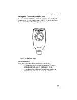
Page 25: ...functions of each button are described in the following pages Figure 7 The camera head buttons Using the P Button The P button controls up to two remote video accessories Press the P button on the camera head for less than one second to activate Remote 1 One beep will sound Press the P button on the camera head for more than one second to activate Remote 2 Two beeps will sound ...

Page 26: ...tch on the rear console panel See the Using the LIGHT ZOOM Switch section of this manual for details Using the Up and Down Buttons The up and down buttons work together to increase or decrease the light level or zoom settings Whether the button selects light or zoom depends on which function has been selected with the LIGHT ZOOM switch on the rear console panel See the Using the LIGHT ZOOM Switch ...

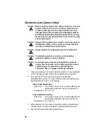
Page 27: ...it with the soaking cap Place the cap over the connector and turn it clockwise until secure Caution Always install the soaking cap before rinsing the camera Failure to properly tighten the soaking cap will corrode the connector pins and void the warranty 2 Rinse the camera head and cable in lukewarm tap water Use a mild enzymatic detergent and a soft brush to remove resistant debris and bioburden ...

Page 28: ...era in sterilization solutions longer than necessary as this will accelerate normal product aging Camera life is extended by the consistent use of a single sterilization method 1 Clean and prepare the camera head and cable as recommended in the Cleaning section Ensure the soaking cap is installed 2 Immerse the camera head and cable in Cidex Plus glutaraldehyde solution or Cidex OPA solution for di...

Page 29: ...Sterilize the camera head and cable with an ethylene oxide sterilization unit according to the following parameters Temperature 55 C 131 F Humidity 70 RH 5 Vacuum 53 34 cmHg 21 inHg Preconditioning time 60 minutes Sterilant mixture 100 ethylene oxide Sterilant concentration 600 5 mg L ethylene oxide Exposure time 120 minutes maximum 180 min Aeration 12 hours 55 C 3 Allow the camera head cable coup...

Page 30: ...o the camera head Any moisture on the threads will cause the camera and coupler windows to fog during use Sterrad System Caution Always install the soaking cap prior to sterilization 1 Clean and prepare the camera head and cable as recommended in the Cleaning and Disinfection sections Ensure the soaking cap is installed 2 Sterilize the camera head and cable using the Sterrad Sterilization System 3...

Page 31: ...ting Warning To avoid the risk of fire only use fuses of the value specified on the fuse label located on the rear panel of the camera control unit 4 Reinstall the fuse holder until the tab snaps in place Periodic Maintenance Schedule Warning To ensure safe operation of the Model 1088 Medical Video Camera you should perform the following procedure periodically Every 12 months check the earth leaka...

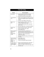
Page 32: ...just the light level with the camera head Decrease the light source output Ensure GAIN is OFF Noise or snow on picture when using electrocautery probes Plug the electrocautery generator into a separate electrical outlet and separate the 1088 power cord from the electrocautery power cord Separate the camera cable from the electrocautery cable Reposition the electrocautery grounding pad on the patie...

Page 33: ...sture that has built up between the two components Optics are dirty Rotate the scope If dust particles in the picture rotate the dust is located on the scope itself Follow the manufacturer s instructions for cleaning the eyepiece and negative lens If particles in the picture do not move when you rotate the scope the particles are located behind the scope Remove the scope and clean the window on th...

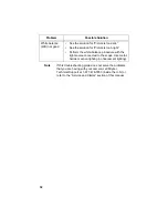
Page 34: ...53 inside the U S or refer to the Service and Claims section of this manual White balance WB not good See the solution for Picture is too dark See the solution for Picture is too bright Perform the white balance procedure with the light source connected to the scope Use metal halide or xenon lighting no fluorescent lighting Problem Possible Solution ...

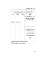
Page 35: ...mal operation of the 1088 Camera in the configuration in which it will be used prior to using it in a surgical procedure Consult the tables below for guidance in placing the 1088 Camera Guidance and Manufacturer s Declaration Electromagnetic Emissions 1088 Camera is intended for use in the electromagnetic environment specified below The customer or the user of 1088 Camera should ensure that it is ...

Page 36: ...mon mode 0 5 1kV differential mode 0 5 1 2kV common mode Mains power quality should be that of a typical commercial or hospital environment Voltage dips short interruptions and voltage variations on power supply input lines IEC61000 4 11 5 Ut 95 dip in Ut for 0 5 cycle 40 Ut 60 dip in Ut for 5 cycles 70 Ut 30 dip in Ut for 25 cycles 5 Ut 95 dip in Ut for 5 sec 5 Ut 95 dip in Ut for 0 5 cycle 40 Ut...

Page 37: ...d separation distance calculated from the equation applicable to the frequency of the transmitter Recommended Separation Distance 80 MHz to 800 MHz 800 MHz to 2 5 GHz where P is the maximum output power rating of the transmitter in watts W according to the transmitter manufacturer and d is the recommended separation distance in meters m Field strengths from fixed RF transmitters as determined by a...

Page 38: ...aintaining a minimum distance between portable and mobile RF communications equipment transmitters and the 1088 Camera system as recommended below according to the maximum output power of the communications equipment Rated maximum output power W of transmitter Separation distance m according to frequency of transmitter 150 kHz to 80 MHz 80 MHz to 800 MHz 800 MHz to 2 5 GHz 0 01 0 12 0 12 0 23 0 1 ...

Page 39: ...ard 1 0V P P 75 Ohms Connector BNC coaxial Y C Two S VHS Y 1 0V P P C 0 29V P P 75 ohms Connector 4 Pin mini DIN Component One RGB R 0 7V p p 75 ohms G 1 0 V p p w SYNC 75 ohms B 0 7 V p p 75 ohms Connector 8 pin DIN Resolution Horizontal 1100 lines Vertical 600 lines Mounting Endoscope Eyepiece used with coupler C mount camera head used with C mount scopes C mount 1 32UN 2A Auto Shutter Range 1 6...

Page 40: ...31 8cm w X 9 7cm h X 38 7cm d Camera Head Cable to Camera Control Unit 10 3 feet 3 15m sealed cable or 20 7 foot 6 30m sealed cable sensed by CCU Enhancement 16 levels switchable Classification Approvals Complies with medical safety standards IEC 60601 1 1988 A1 1991 A2 1995 IEC 60601 2 18 1996 A1 2000 CAN CSA C22 2 No 601 1 M90 UL2601 1 2nd Edition AS NZS 3200 1 0 1998 Complies with medical EMC s...

Page 41: ...s of operation the repairs will be billed to the customer as out of warranty repairs Instruments repaired under Stryker Endoscopy s standard repair program will be issued a thirty day warranty against defects in both materials and workmanship provided the original warranty period has passed Instruments submitted due to defects in materials and workmanship during the warranty period will be repaire...

Page 42: ...d If service is needed either during or after the warranty period 1 Contact Stryker Endoscopy at 1 800 624 4422 or phone your local Stryker Endoscopy sales representative 2 Package all the components carefully in the original shipping container if possible 3 Ship the camera pre paid and insured to Stryker Endoscopy Customer Service Attention Repair Department 5900 Optical Court San Jose CA 95138 S...

Page 43: ...d GmbH Gewerbeallee 18 D 45478 Mulheim an der Ruhr GERMANY Phone 49 208 999 060 Fax 49 208 999 0666 Stryker Australia No 50 Broughton Road Artarmon NSW 2064 AUSTRALIA Phone 61 2 9415 5100 Fax 61 29 4294127 Stryker Latin America 15100 N W 67th Ave Suite 210 Miami Florida 33014 USA Phone 1 305 821 1888 Fax 1 305 826 0067 Stryker Singapore PTE LTD 70 Bendemeer Road 03 32 Hiap Huat House SINGAPORE 339...

Page 44: ...tiago CHILE Phone 562 244 3600 Fax 562 244 3696 Stryker Japan Dai Tokyo Kasai Shinjuku Bldg 3 25 3 Yoyogi Shibuya ku Tokyo 151 0053 Phone 813 535 29106 Fax 813 535 21789 Stryker Spain Manuel Tovar 35 28034 Madrid SPAIN Phone 34 91 7283500 Fax 34 91 3580748 Stryker Europe Headquarters Cite Centre Grand Rue 92 CH 1820 Montreux SWITZERLAND Phone 41 21 966 1201 Fax 41 21 966 1200 Stryker AB Scandinavi...

Page 45: ......

Page 46: ...5900 Optical Court San Jose CA 95138 1 800 624 4422 1 800 729 2917 1000 400 675 Rev A ...

Reviews: