background image

Electromagnetic Compatibility Tables

27

Like other electrical medical equipment, the X7000 requires special 

precautions to ensure electromagnetic compatibility with other electrical 
medical devices. To ensure electromagnetic compatibility (EMC), the 
X7000 must be installed and operated according to the EMC information 
provided in this manual. 

Note

The X7000 has been designed and tested to comply with 
IEC 60601-1-2:2001 requirements for EMC with other 
devices.

Caution

Portable and mobile RF communications equipment may 
affect the normal function of the X7000.

Warning Do not use cables or accessories other than those 

provided with the X7000, as this may result in 
increased electromagnetic emissions or decreased 
immunity to such emissions.

Warning

If the X7000 is used adjacent to or stacked with other 
equipment, observe and verify normal operation of the 
X7000 in the configuration in which it will be used prior 
to using it in a surgical procedure. Consult the tables 
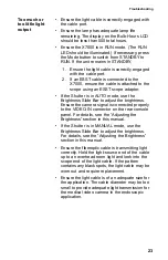
below for guidance in placing the X7000.

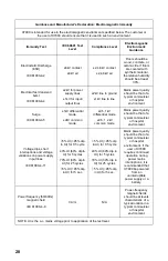
Guidance and Manufacturer's Declaration: Electromagnetic Emissions

X7000 is intended for use in the electromagnetic environment specified below. The customer or the 

user of X7000 should ensure that it is used in such an environment.

Emissions test

Compliance 

Electromagnetic Environment - guidance

RF emissions CISPR

11

Group 1

X7000 uses RF energy only for its internal 

function; therefore, its RF emissions are very 

low and are not likely to cause any interference 

in nearby electronic equipment.

RF emissions CISPR

11

Class B

X7000 is suitable for use in all establishments, 

including domestic establishments and those 

directly connected to the public low-voltage 

power supply network that supplies buildings 

used for domestic purposes.

Harmonic emissions

IEC61000-3-2

Class A

Voltage Fluctuations/

flicker emissions

IEC61000-3-3

Complies

Electromagnetic Compatibility 

Summary of Contents for X7000

Page 1: ......

Page 2: ......

Page 3: ...e 13 Adjusting the Brightness 13 Receiving Feedback from the X7000 14 Safety Shutoff 15 Checking the ESST Feature 16 Using the X7000 with a Voice Controlled System Interface 16 Using the Ethernet Interface 17 Cleaning and Maintenance 18 Cleaning the X7000 18 Caring for the Lamp Module 18 Replacing the Lamp Module 19 Replacing the Fuses 21 Disposing of the X7000 21 Troubleshooting 22 Technical Spec...

Page 4: ...2 Other Service 33 ...

Page 5: ...warn of the presence of hazardous voltage Refer all service to authorized personnel To avoid potential serious injury to the user and the patient and or damage to this device the user must 1 Read this operating manual thoroughly and be familiar with its contents prior to using this equipment 2 Carefully unpack the unit and check if any damage occurred during shipment If damage is detected please r...

Page 6: ... described herein Product s therefore may not agree in detail with the published design or specifications All specifications are subject to change without notice Please contact the local Stryker Endoscopy Distributor listed in the Other Service section or phone your local Stryker Endoscopy sales representative or agent for information on changes and new products Warning Federal law United States o...

Page 7: ...y ESST a special safety feature that helps prevent accidental burns caused by an unattended light cable When operated with an ESST light cable the X7000 senses when the scope and the light cable are separated and places the light source in STANDBY mode In STANDBY mode the X7000 will reduce light output to a minimum preventing the light cable from generating excessive heat The Stryker Endoscopy X70...

Page 8: ...6 Figure 1 The X7000 console front panel top and rear panel bottom 4 3 2 1 5 6 7 8 9 10 11 12 13 14 15 16 17 18 ...

Page 9: ... LED Illuminates when the shutter is in the AUTO mode In AUTO mode light output is determined by the brightness setting and the input video signal 9 Jaw Handle Opens the fiberoptic cable holder 10 Cable Clamp Grasps the light source end of an inserted fiberoptic cable When no cable is inserted the lamp automatically turns off to save bulb hours 11 MANUAL LED Illuminates when the shutter is in the ...

Page 10: ...r the equipment has arrived Note When selecting a setup location for the X7000 consult the Electromagnetic Compatibility section included in this manual to determine the best location To set up the X7000 make the following connections Connect the AC power cable Connect the camera and monitor Connect the light cable Connecting the AC Power Cable 1 Plug in the AC power cord to the AC Inlet on the re...

Page 11: ... port b on the rear panel of the camera 3 Connect a DVI cable to the DVI Out 1 c on the rear panel of the camera 4 Connect the other end of the DVI cable to the DVI input d on the rear of the flat panel monitor Note BNC cables have push and turn connectors DVI cables have push only 29 pin connectors Warning When the X7000 is interconnected with other medical electrical equipment leakage currents m...

Page 12: ...tible with all Stryker Light Cables 1 Lock open the cable clamp by turning the jaw handle clockwise until it stops see Figure 3 Figure 3 Locking open the cable clamp Warning Keep fingers away from the cable clamp as the clamp may inadvertently deploy and cause injury Warning Do not look directly into the cable port The high intensity light may cause damage to the eyes ...

Page 13: ...tly on the fiber optic cable to test that it is securely seated in the cable port Figure 4 Inserting the light cable into the cable port 3 Connect an endoscope to the opposite end of the fiber optic cable 4 To remove the light cable turn the jaw handle clockwise until it latches fully open Note The Light Source will default to STANDBY mode when a light cable is inserted ...

Page 14: ...lled lamp If no lamp is installed follow the instructions in the Replacing the Lamp section of this manual before proceeding 2 Press the power switch on the front panel The STANDBY LED will illuminate indicating the unit is in STANDBY mode Note The lamp will not illuminate unless a light cable is installed in the cable port To power off the X7000 1 Disconnect the light cable from the X7000 console...

Page 15: ...tings for adjusting the lamp brightness AUTO and MANUAL AUTO shutter The AUTO shutter automatically adjusts brightness to compensate for variable light levels in the surgical site Receiving input from the medical camera the AUTO shutter adjusts light levels around the brightness selected on the Brightness LCD For optimal AUTO shutter performance use the Brightness Slide Bar to set the brightness b...

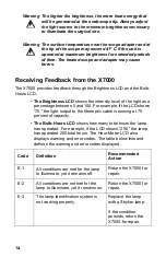
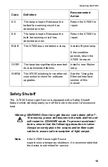
Page 16: ... percentage between 0 and 100 For example if the LCD shows 75 the light output to the fiberoptic cable is running at 75 percent of capacity The Bulb Hours LCD shows how many total hours the lamp has operated For example if the LCD shows 250 the lamp has operated 250 total hours The Hour Meter LCD also displays warning and error codes The table below lists and defines the warning and error codes di...

Page 17: ...on Light Source experiences a temporary shutdown it is recommended that the device is submitted for service E 5 The lamp is kept off because the ballast fan sensing circuit has detected an error Return the X7000 for repair E 6 The lamp is kept off because the bulb fan sensing circuit has detected an error Return the X7000 for repair BULB The X7000 does not detect a lamp Install a Stryker lamp If t...

Page 18: ...efore every surgical procedure 1 Set up the X7000 system with an ESST light cable and scope and then power on the system 2 Place the X7000 in RUN mode 3 Remove the light cable from the ESST scope adapter The X7000 should return to STANDBY mode indicating that the ESST feature is functioning properly Warning If the unit fails to return to STANDBY mode there may be a fault with the ESST feature In t...

Page 19: ...le to the Ethernet Port on the rear console panel and the other end to the existing hospital network Note The hospital network must have a Dynamic Host Configuration Protocol DHCP server that can assign an IP address to the unit 2 Power on the X7000 The unit will search for download and install any necessary software updates It may also transmit diagnostic information This period will typically ta...

Page 20: ...mp face with alcohol and a cotton swab if it is touched Dirt or oil on the lamp face will cause the lamp to heat unevenly and fail 2 Do not power on and off the lamp in rapid succession Allow the lamp to run for at least five minutes once it has been powered on Failure to do so can cause the lamp to rapidly darken and fail 3 The X7000 has been designed to start the lamp under most conditions even ...

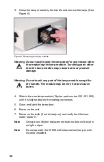
Page 21: ... If possible replace the lamp module between surgical procedures Warning During operation the lamp and the housing around the lamp may be hot Wait at least three minutes for the lamp to cool before handling it To replace the lamp module 1 Power down the X7000 2 Open the lamp door see Figure 5 Figure 5 Opening the lamp door Note If the unit is on opening the lamp door will turn off the bulb ...

Page 22: ...uch any part of the lamp module except for the handle The module may be very hot and cause burns 4 Slide in the new lamp module Stryker part number 220 191 000 until it is fully seated on the mating connectors 5 Close and latch the lamp door 6 Power on the unit 7 Power on the bulb if not already on and verify that the hour meter reads 0 Note Using a non Stryker replacement bulb module will result ...

Page 23: ...t 2 Unlatch the fuse holder 13 and remove the fuse s 3 Replace the fuse s with the same value and rating Warning To avoid the risk of fire use only 5 0A 250V fuses 4 Reinstall the fuse holder Disposing of the X7000 The device must be disposed of according to local laws and hospital practices The device does not contain any hazardous materials ...

Page 24: ... Ensure the lamp is in operating condition Replace the lamp if necessary Ensure the light cable is correctly engaged with the cable port As a safety feature the X7000 will provide no light output unless a fiberoptic light cable is properly seated in the cable port Ensure the bulb access door is completely shut Check for error codes E 1 E 3 E 5 E 6 or BULB See the Receiving Feedback from the X7000 ...

Page 25: ...ss Slide Bar to adjust the brightness Ensure the camera signal is connected properly to the VIDEO IN connector on the rear console panel For details see the Adjusting the Brightness section in this manual If the Shutter is in MANUAL mode use the Brightness Slide Bar to adjust the brightness For details see the Adjusting the Brightness section in this manual Ensure the fiberoptic cable is transmitt...

Page 26: ...py has designed the AUTO shutter feature of the X7000 for use only with Stryker Endoscopy medical video cameras The AUTO feature may not provide sufficient light when connected to non Stryker Endoscopy medical video cameras If the Shutter is in MANUAL mode ensure the electronic shutter on the camera is operating properly to control video signal brightness Adjust the brightness control setting as n...

Page 27: ...ately 500 hours Operating Conditions 10 to 40 C 30 to 75 Relative Humidity Transportation Storage 20 to 60 C 10 to 75 Relative Humidity 700hPa to 1060hPa Classifications Approvals Complies with medical safety standards IEC60601 1 1988 A1 1991 A2 1995 CAN CSA C22 2 No 601 1 M90 UL2601 1 2nd Edition Complies with medical EMC standard IEC60601 1 2 2001 Class 1 Equipment Type CF applied parts Water In...

Page 28: ...26 Patent Protection U S 5 850 496 and 6 110 107 Other patents pending Stryker European Representative Stryker France ZAC Satolas Green Pusignan Av De Satolas Green 69881 MEYZIEU Cedex France ...

Page 29: ...mal operation of the X7000 in the configuration in which it will be used prior to using it in a surgical procedure Consult the tables below for guidance in placing the X7000 Guidance and Manufacturer s Declaration Electromagnetic Emissions X7000 is intended for use in the electromagnetic environment specified below The customer or the user of X7000 should ensure that it is used in such an environm...

Page 30: ...mon mode 0 5 1kV differential mode 0 5 1 2kV common mode Mains power quality should be that of a typical commercial or hospital environment Voltage dips short interruptions and voltage variations on power supply input lines IEC61000 4 11 5 Ut 95 dip in Ut for 0 5 cycle 40 Ut 60 dip in Ut for 5 cycles 70 Ut 30 dip in Ut for 25 cycles 5 Ut 95 dip in Ut for 5 sec 5 Ut 95 dip in Ut for 0 5 cycle 40 Ut...

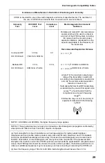
Page 31: ...termined by an electromagnetic site survey a should be less than the compliance level in each frequency range b Interference may occur in the vicinity of equipment marked with the following symbol NOTE 1 At 80 MHz and 800 MHz the higher frequency range applies NOTE 2 These guidelines may not apply in all situations Electromagnetic propagation is affected by absorption and reflection from structure...

Page 32: ...ce m according to frequency of transmitter 150 kHz to 80 MHz 80 MHz to 800 MHz 800 MHz to 2 5 GHz 0 01 0 12 0 12 0 23 0 1 0 37 0 37 0 74 1 1 17 1 17 2 33 10 3 70 3 70 7 37 100 11 70 11 70 23 30 For transmitters rated at a maximum output power not listed above the recommended separation distance d in meters m can be estimated using the equation applicable to the frequency of the transmitter where P...

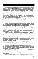
Page 33: ... workmanship provided the original warranty period has passed Instruments submitted due to defects in materials and workmanship during the warranty period will be repaired at no charge to the customer The warranty as set forth herein is exclusive and in lieu of all other warranties remedies obligations and liabilities of Stryker Endoscopy Inc expressed or implied including the implied warranties o...

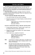
Page 34: ...ourt San Jose CA 95138 If service is needed either during or after the warranty period 1 Contact Stryker Endoscopy at 1 800 624 4422 or phone your local Stryker Endoscopy sales representative 2 Package all the components carefully in the original shipping container if possible 3 Ship the light source prepaid and insured to Stryker Endoscopy Customer Service Attention Repair Department 5900 Optical...

Page 35: ...chland GmbH Gewerbeallee 18 D 45478 Mulheim an der Ruhr GERMANY Phone 49 208 999 060 Fax 49 208 999 0666 Stryker Australia No 50 Broughton Road Artarmon NSW 2064 AUSTRALIA Phone 61 2 9415 5100 Fax 61 29 4294127 Stryker Latin America 15100 N W 67th Ave Suite 210 Miami Florida 33014 USA Phone 1 305 821 1888 Fax 1 305 826 0067 Stryker Singapore PTE LTD 70 Bendemeer Road 03 32 Hiap Huat House SINGAPOR...

Page 36: ...tiago CHILE Phone 562 244 3600 Fax 562 244 3696 Stryker Japan Dai Tokyo Kasai Shinjuku Bldg 3 25 3 Yoyogi Shibuya ku Tokyo 151 0053 Phone 813 535 29106 Fax 813 535 21789 Stryker Spain Manuel Tovar 35 28034 Madrid SPAIN Phone 34 91 7283500 Fax 34 91 3580748 Stryker Europe Headquarters Cite Centre Grand Rue 92 CH 1820 Montreux SWITZERLAND Phone 41 21 966 1201 Fax 41 21 966 1200 Stryker AB Scandinavi...

Page 37: ......

Page 38: ...5900 Optical Court San Jose CA 95138 1 800 624 4422 1 800 729 2917 1000 400 651 Rev C ...


Reviews: