


0940-001-025 Rev-L
EN
www.stryker.com
9
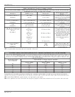
Troubleshooting
WARNING:
DO NOT disassemble or service this equipment, unless
otherwise specified.
NOTE:
For service, contact your Stryker sales representative or call Stryker
customer service. Outside the US, contact your nearest Stryker subsidiary.
PROBLEM
CAUSE
SOLUTION
The Cast Cutter does
not operate.
The Cast Cutter is not
connected to facility
power.
See the
To Connect the
Cast Cutter to a Power
Source
section.
The motor brushes are
installed in the wrong
orientation.
Remove and install the
motor brushes. See the
Inspection, Testing, and
Maintenance
section.
The function switch is
broken.
Return the Cast Cutter
to Stryker for repair.
The fuse is blown.
Return the Cast Cutter
to Stryker for repair.
The Cast Cutter
operates at a very low
speed.
The motor brushes are
installed in the wrong
orientation.
Remove and install the
motor brushes. See the
Inspection, Testing, and
Maintenance
section.
The Cast Cutter does
not operate smoothly,
or operates with
excessive noise.
The motor brushes are
worn.
Replace the motor
brushes and springs.
See the
Inspection,
Testing, and
Maintenance
section.
The roller bearing is
worn.
Return the Cast Cutter
to Stryker for repair.
The blade does not cut
smoothly.
The blade is worn.
Replace the blade. See
the
Instructions
section.
The blade slips.
The blade guide posts
are worn.
Return the Cast Cutter
to Stryker for repair.
When used with a
CastVac, the level of
suction is reduced.
The vacuum hood is
blocked with debris.
Remove the debris from
the vacuum hood. See
the
Cleaning
section.
The equipment
experiences sporadic
electrical interference.
Electrical noise is
present.
Turn off all electrical
equipment not in use.
Relocate electrical
equipment; increase
spatial distance
between devices.
Connect electrical
equipment to different
facility power outlets.


