


0940-001-025 Rev-L
EN
www.stryker.com
3
Accessories
WARNINGS:
▪
Use only Stryker-approved system components and accessories, unless
otherwise specified. Failure to comply may result in fire, electric shock,
or injury.
▪
Using other electronic components and accessories may result in
increased electromagnetic emissions or decreased electromagnetic
immunity of the system.
NOTE:
For a complete list of accessories, contact your Stryker sales
representative or call Stryker customer service. Outside the US, contact your
nearest Stryker subsidiary.
This section describes system components that may be ordered to replace
original equipment that is damaged, worn, or must be replaced. This section
may also contain optional components used with the system.
The following Stryker-approved accessories are sold separately:
DESCRIPTION
REF
Small Cast Spreader
0082-000-000
Large Cast Spreader
0083-000-000
Cast Cutter Blades
0940-XXX-XXX series
Blade Tool
0940-050-000
Vacuum Line Cap
0940-001-135
CastVac™
0986-000-000
0987-000-000
0996-000-000
Adaptor Hose with Cord (to connect Cast
Cutter REF 0940-000-000 to Stryker
PlasterVac™ REF 0886-000-000)
0940-886-000
Adaptor Hose with Cord (to connect Cast
Cutter REF 0940-000-000 to Stryker
PlasterVac REF 0846-000-000 or
0856-000-000)
0940-855-000
Adaptor Hose with Cord (to connect Cast
Cutter REF 0940-000-000 to Stryker
OrthoVac™ REF 0864-000-000)
0940-864-000
Cast Cutter Repair Kit
0940-001-140Q
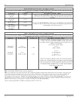
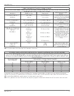
WARNING:
When using a Stryker CastVac, ALWAYS connect the Cast
Cutter to a CastVac with an appropriate voltage. Failure to comply may
result in fire, electric shock, or injury.
CAST CUTTER REF
VOLTAGE
CASTVAC REF
0940-000-000
100-120 V
0986-000-000
0987-000-000
0941-000-000
220-240 V
0996-000-000
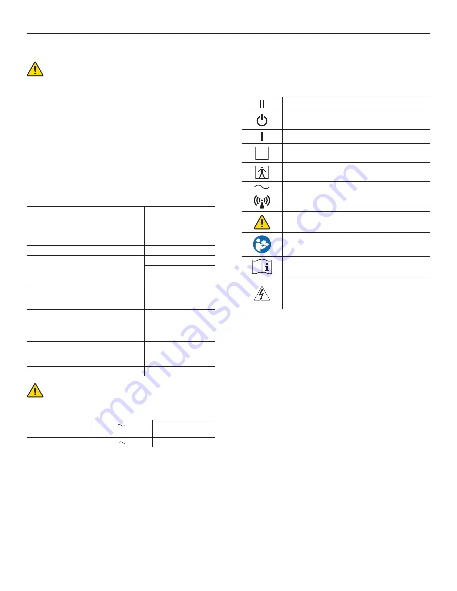
Definitions
The symbols located on the equipment and/or labeling are defined in this
section or in the
Symbol Definition Chart
. See the
Symbol Definition Chart
supplied with the equipment.
SYMBOL
DEFINITION
High Speed Mode
Standby Mode
Standard Speed Mode
Class II equipment (Double Insulation)
Type BF Applied Part
Alternating current (AC)
Non-ionizing electromagnetic radiation
General warning sign
Refer to instruction manual/booklet
Consult instructions for use
This symbol is intended to alert service personnel of the
presence of voltage that may cause injury or fatal electric
shock. Disconnect the device from the electrical supply
before servicing.


