background image

29

9.  Room Camera

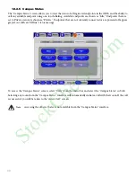
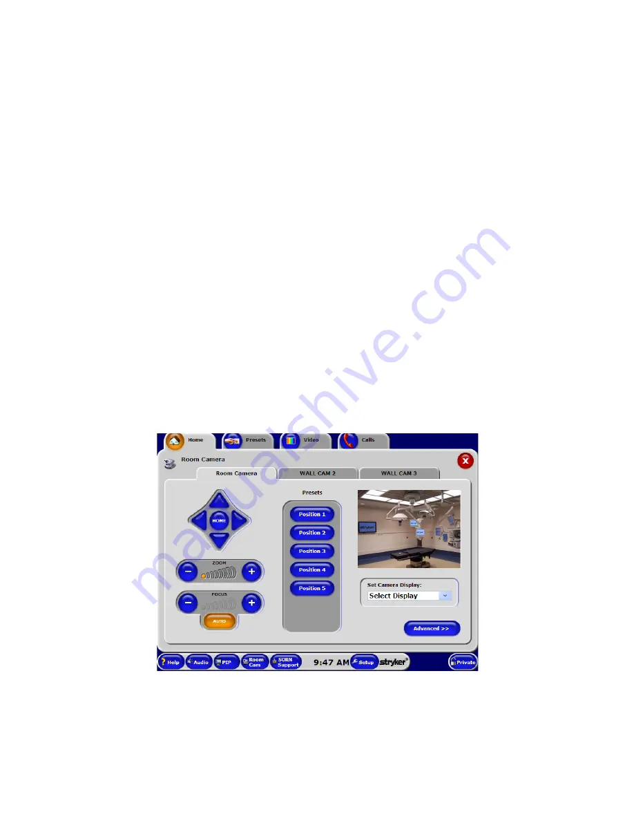
The “Room Camera” screen directs the operation of the wall-mounted pan / tilt / zoom cameras in the OR. This 
screen allows you to adjust the pan/tilt/zoom functions as well as to focus the camera to frame the action. There 
are two ways to access the “Room Camera” screen: 

1. Select the 

Room Camera

 button from the “Home” screen.  

2. Press the 

Room Camera

 quick button in the task bar at the bottom of the screen.

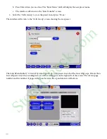
Each camera can be panned left or right, tilted up and down, and zoomed in and out. The Focus can be controlled 
automatically by selecting the 

Auto Focus

 button, but can be adjusted manually for unusual lighting conditions or 

camera angles.

To access pan/tilt/zoom camera controls:

1. Select one of the available room cameras from the sub tabs at the top of the screen. 

2. Direct the camera by pressing and holding the button that corresponds to the direction that you want the 

camera to pan or tilt. For example, press and hold the “left arrow” button to move the camera head from 
right to left. The

 Zoom

 and 

Focus

 controls operate in the same manner.

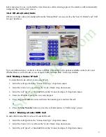
Once you have established camera angles and zoom preferences, you can save it as a preset by pressing and 
holding down on one of the five preset buttons until the message, “The Position Has Been Saved” appears just 
below the preset buttons.

To recall a saved camera position, press the numbered button (i.e., Position 1) that corresponds to the camera 
preset. The camera will quickly return to that position.

StockCheck.com

Summary of Contents for SwitchPoint Infinity 2

Page 1: ...571 Silveron Blvd Flower Mound TX 75028 972 410 7000 877 789 8106 February 2014 1004 400 078 REV F SwitchPoint Infinity 2 Operations and Maintenance Manual Control System S t o c k C h e c k c o m ...

Page 2: ...ntenance Manual contains confidential information that shall not be disclosed or duplicated for any reason other than to use and maintain a SWITCHPOINT INFINITY 2 CONTROL SYSTEM This restriction does not limit the right to use information contained in this manual if it is obtained from another source without restriction The information subject to this restriction is contained in all pages of this ...

Page 3: ...uts 11 5 2 3 Audio Inputs 11 5 2 4 Audio Outputs 11 5 2 5 RS 232 Connectivity 12 5 2 6 Relays 12 5 2 7 Voltage In Voltage Out 12 5 2 8 Infrared 12 5 2 9 KVM 12 5 2 10 Video Network Hub 12 5 2 11 Sidne Voice Activation System 12 5 2 12 OR Based Conferencing Equipment 12 5 2 13 Local Codec 13 6 The Touch Panel Interface 14 6 1 Touch Panel Interface 14 6 2 Touch Panel Functions 15 6 2 1 Menu Bar 15 6...

Page 4: ...12 2 3 Active Call 36 12 2 4 Private 37 12 2 5 Campus Status 38 12 2 6 Last 10 Dialed 39 12 3 Call Groups 39 12 3 1 Creating and Storing a Call Preset 39 12 4 Off site Codec Calls 41 12 5 Making a Codec IP Call 41 12 5 1 Making a Codec ISDN Call 41 12 5 2 Making a Codec Gateway Call 42 12 5 3 Wait for off site 42 12 6 Advanced Call Types 43 12 6 1 Broadcast 43 12 6 2 View Only 44 12 6 3 Meeting Ro...

Page 5: ...lor Is Unusual Or Rolling On The Flat Panel Display 61 21 3 5 Connecting External Video Devices 62 21 4 Troubleshooting Audio 62 21 4 1 Audio Not Leaving The Room 62 21 4 2 No Audio In The Room 62 21 5 Troubleshooting High Resolution Switching 63 21 5 1 Flat Panel Not Switching Properly Between Video and High Resolution 63 21 5 2 Image Not Properly Sized On Flat Panel 63 21 5 3 Wrong Image Being D...

Page 6: ...structed to do so in this manual 6 The electrical installation of the relevant operating room complies with the applicable IEC CEC and NEC requirements WARNING Wireless Microphone The wireless microphone functionality included in this device contains a radio transmitter and receiver Hospitals and health care facilities may be using equipment that is sensitive to RF frequencies Prior to using this ...

Page 7: ...cations 4 Federal law United States of America restricts this device to use by or on the order of a physician 1 3 Notes 1 The warranty on this product is void if any of these warnings are disregarded 2 Disconnect the unit from the electrical outlet before inspecting system components 3 Stryker Communications has verified that the SwitchPoint Infinity 2 Control System complies with the electromagne...

Page 8: ...diac Application When this symbol appears on a device it refers the user to the Operations and Maintenance manual for important safety information When it appears in the manual it is meant to alert the user to the presence of important safety operating and maintenance instructions A lightning bolt within a triangle is intended to warn of the presence of hazardous voltage Refer all service to autho...

Page 9: ...ve 2002 96 EC on Waste Electrical and Electronic Equipment this symbol indicates that the product must not be disposed of as unsorted municipal waste but should be collected separately Denotes the device contains more than 002 cadmium Denotes the device contains more than 0005 mercury Denotes the device contains more than 004 lead S t o c k C h e c k c o m ...

Page 10: ...icating operating voltage power consumption etc is located on the front Should any liquid enter the SwitchPoint Infinity chassis unplug the unit and have it checked by qualified personnel before operating it any further To disconnect the AC power cord pull it out by grasping the plug Never pull the cord itself The socket outlet shall be installed near the equipment and shall be easily accessible 3...

Page 11: ... intent of the SwitchPoint Infinity 2 Control System is to allow operating room personnel a center point for controlling all equipment and communication in surgery The Stryker SwitchPoint Infinity 2 Control System is indicated for use with the Stryker Endoscopy Sidne System 510 k K022393 and Sidne compatible endoscopic and general surgery devices The users of SwitchPoint Infinity 2 Control System ...

Page 12: ...ctions optional A6 2 RGB HV Outputs for Touch Panel Connection D RS 232 Connectivity A7 1 S Video Output for Video Preview D1 16 RS 232 ports for serial communications A8 1 S Video Input for Video Preview with external devices A9 2 RS 232 Communications Ports for Touch Panel Control A10 1 Ethernet Port E Expansion System A11 1 PS 2 Mouse Port and Keyboard Port E1 4 KVM Inputs A12 1 USB Port E2 1 K...

Page 13: ...c devices 5 2 2 Video Outputs There are 8 DVI optional 14 RGB HV optional and 14 S Video outputs available to send video directly to flat panel displays monitors projectors and other video device inputs All of the connections are located on the front panel For video output wiring connect device input to an available video output on the SwitchPoint Infinity 2 Control System connection panel Any vid...

Page 14: ...oom connectivity for video conference If your system is equipped with a Codec the Codec will be housed in the Video Network Hub and will allow off site connectivity The Video Network Hub is connected to the SwitchPoint Infinity 2 Control System using the Audio In and Out connectors the Ethernet connection and the video input and output connectors Details of the connection and operation of the Vide...

Page 15: ...le connections to the SwitchPoint Infinity 2 Control System must be synchronized with the software This configuration is maintained in the Advanced Setup area of the user interface Changing cable connections without changing the software configuration will result in system malfunction Contact technical support for assistance S t o c k C h e c k c o m ...

Page 16: ...ers a menu of options dependent on the equipment that is installed in that particular room To use the touch panel simply touch the displayed button with the soft surface of your finger The SwitchPoint Infinity 2 Control System touch panel interface is divided into three main sections the Menu Bar the Control Section and the Taskbar S t o c k C h e c k c o m ...

Page 17: ... the SwitchPoint Infinity 2 Control System Calls The Calls menu controls the connection of the SwitchPoint Infinity 2 Control System to various rooms within the hospital campus It also provides access to off site locations using a Codec installed in the Video Network Hub Note Most styluses cannot be used on the SwitchPoint Infinity 2 Control System s touch panel interface For best results use your...

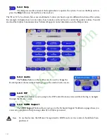
Page 18: ...upport contact information in the Help section 6 2 4 Audio The Volume button on the taskbar can be used to change the Room Speaker volume without having to go to the Audio Levels screen 6 2 5 PIP The PIP button allows you to jump to the PIP control from any screen without having to navigate through the Home screen 6 2 6 SORN Support The SORN Support button allows you to go to the Technical Support...

Page 19: ...nced Controls devices that are connected to the SwitchPoint Infinity 2 Control System For example the Video Router button controls all of the routing functions within the room while the Room Camera button sets up and operates the pan tilt zoom cameras located within the room To access the Home screen select the Home tab from the Menu Bar The PC Controls section has buttons that allow you to access...

Page 20: ...ontains an item that requires naming such as Presets or Calls Use the alphanumeric keys on the keyboard to name a button Once completed press the Done button to continue To cancel naming a button press the red X button at the top right hand corner of the screen S t o c k C h e c k c o m ...

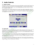
Page 21: ...el screen provides the ability to change the audio input levels such as the surgeon s wireless microphone The SwitchPoint Infinity 2 Control System supports up to 10 audio inputs including two inputs for the CD Player To access the Input Levels tab select the Audio Levels button from the Home screen and press the Input Levels sub tab Each audio input level has a volume level indicator bar to show ...

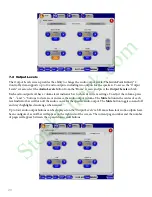
Page 22: ...rent settings To adjust the volume press the and buttons to decrease or increase the audio output volume The Mute button in the center of each level indicator bar will turn off the audio source for the specific audio output The Mute button toggles on and off and stays highlighted in orange when muted Up to four audio output buttons can be displayed on the Output Levels tab If more than four audio ...

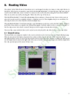
Page 23: ... 2 Control System gives special distinction to devices such as the SDC Sidne Printers and VCRs These devices are capable of receiving video signals but their output can be re routed to a display so that the surgeon can view what is currently being recorded on a given documentation device There are three ways in which video can be routed each of which will be described in the sections that follow 8...

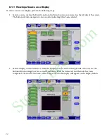
Page 24: ...he button will turn orange for a few seconds indicating it has been selected 2 Select a display such as Monitor 2 from the Displays area located on the right side of the screen The button will turn orange for a few seconds indicating it has been selected and the route has been completed The icon for the video source being routed to the display will appear on the display button S t o c k C h e c k ...

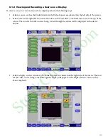
Page 25: ...ice through which to route the source such as the SDC from the Devices area at the top of the screen The icon for the video source being routed through the device will be displayed on the device button 3 Select a display such as Monitor 2 from the Displays area located on the right side of the screen The icon for the video source being routed through the display will appear on the display button T...

Page 26: ...s in the Preview area of the touch panel and that on the display monitor are not the same The video that appears in the Preview area of the touch panel is passed directly from the input source The input video is then passed through the SDC HD which is then displayed on the monitor This means that for SDC HD only the Record and other textual overlays will not be displayed on the SPI 2 preview but t...

Page 27: ...section shows a list of all available sources devices and displays the lower right corner displays the video preview pane Note that in the figure above each source device and display is color coded Each color represents the video route available to the specific component Blue represents a DVI video type red represents high resolution and yellow represents S video Some components can be routed thro...

Page 28: ...the example shown in the figure the route begins with the Endo Cam which is then passed through Monitors 1 and 3 as well as the Sidne device The route continues from Sidne through the SDC and ends at Monitor 2 You can further see through the route in the figure above that each of the chosen components are capable of using the DVI Hi Res and S Video types The colored arrows pointing between each of...

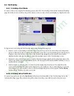
Page 29: ...op right corner of the Text Routing screen 2 If desired select a device to record to or redirect the video image using the device drop down menu The video source will be routed to the selected device and the ouptut of that device will be available to route to another device or display 3 Select a display to view the source or device from the display drop down menu The output from the source will im...

Page 30: ...e image loss at the SwitchPoint Infinity the system is designed with a video fail safe mode When powered off the SwitchPoint Infinity will automatically route the designated preferred care video directly to the primary video monitor The user must manually change the video source on the primary video monitor to RGBHV or equivalent preferred care video format to display this image S t o c k C h e c ...

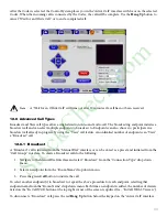
Page 31: ...amera angles To access pan tilt zoom camera controls 1 Select one of the available room cameras from the sub tabs at the top of the screen 2 Direct the camera by pressing and holding the button that corresponds to the direction that you want the camera to pan or tilt For example press and hold the left arrow button to move the camera head from right to left The Zoom and Focus controls operate in t...

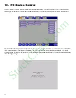
Page 32: ... System keyboard mouse and monitor The SwitchPoint Infinity 2 Control System interface can be configured with one touch buttons for a PACS PC a NAV Navigation PC and an AUX Auxiliary PC Press the button on the SwitchPoint Infinity 2 Control System Home screen for the target PC to be controlled the SwitchPoint Infinity 2 Control System will display the following message S t o c k C h e c k c o m ...

Page 33: ...C Control is returned to the SwitchPoint Infinity 2 Control System by tapping the touch panel twice Note The touch panel functionality does not control target PCs Touching the screen while controlling a target PC will return control to the SwitchPoint Infinity 2 Control System interface S t o c k C h e c k c o m ...

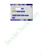
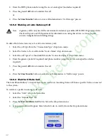
Page 34: ... the SwitchPoint Infinity 2 Control System Press the Save Preset button on the Presets screen The Save Preset screen will appear as shown above 1 Select the white text field or the Edit button next to the Enter Name field A keyboard screen will appear 2 Enter the preset name using the on screen keyboard that appears or the attached keyboard The preset name can be no longer than 13 characters inclu...

Page 35: ...33 S t o c k C h e c k c o m ...

Page 36: ... system is not equipped with a Video Network Hub or locally connected Codec the Calls menu and Private buttons will be grayed out and not accessible In addition to manual dialing the Calls feature supports one touch calling of any connected endpoint from the Campus Status screen one touch dialing of the Last 10 Dialed and up to 200 presets in the Call Groups section 12 2 Making a Call Calls can be...

Page 37: ...odec call To access the Manual Dial tab select Calls from the menu bar and then select the Manual Dial tab on the Calls screen 12 2 2 Room to Room Call To make a video call to another room within the campus 1 Select Room from the Connection Type drop down menu Note For in depth information on local and Video Network Hub Codec call please see the Offsite Codec Calls section of this manual Note For ...

Page 38: ...h camera to control during a call The camera controls work in the same manner as the Room Camera controls on the Room Camera interface The What you send and Where you see it drop down menus are convenient ways to route video to and from the remote connection The What you send option on the Active Call screen displays a preview of the remote room s video image to a local display When the far video ...

Page 39: ...d and outbound communications If the SwitchPoint Infinity 2 Control system is currently connected to another room within the hospital campus or off site location activating the Private feature will immediately disconnect the room When Private is On you can still make outgoing calls to other rooms The Private On state is restored after the call If you attempt to connect to a room that is In Private...

Page 40: ...dpoints that are not currently connected or are powered off appear grayed out with an Offline status message To access the Campus Status screen select Calls from the menu bar and select the Campus Status sub tab Selecting any room from the Campus Status interface will automatically initiate a call with that room If the call is successful you will be taken to the Active Call screen Note Accessing t...

Page 41: ...h the What you send and Where you see it drop down menus 12 3 Call Groups The Call Groups tab provides call specific presets for call types available from the SwitchPoint Infinity 2 Control Interface Once a Preset is stored in the Call Groups section the call can be placed using one touch dialing from the Call Groups tab Note Before storing a new Preset in the Call Groups section enter the connect...

Page 42: ...The interface will return to the Calls Group screen showing the new preset The SwitchPoint Infinity 2 Control System supports up to 50 presets in each of the four call groups If more than four call presets have been configured a scroll bar will appear on the right side of the screen The current page number and the number of pages will appear between the up and down scroll buttons S t o c k C h e c...

Page 43: ...al Codec IP call 1 Select the call type from the Connection Type drop down menu 2 Select the Codec to be used from the Codec Name drop down menu 3 Select the call speed or bandwidth from the Connection Speed drop down menu 4 Enter the IP address using the on screen keypad 5 Press the green Call button located below the number pad to initiate the call or 6 Press the Store Number button to store the...

Page 44: ...he Codec to be used from the Codec Name drop down menu 3 Select the call speed or bandwidth from the Connection Speed drop down menu 4 Enter the gateway prefix if required and phone number using the on screen keypad no dashes required 5 Press the green Call button to initiate the call or 6 Press the Store Number button to store the call information to Call Groups presets 12 5 3 Wait for Offsite Ca...

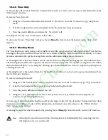
Page 45: ...mited number of endpoints can View a Broadcast call 12 6 1 Broadcast A Broadcast call is initiated from the Manual Dial interface or can be stored as a preset and initiated from the Call Groups interface To create a Broadcast call do the following 1 Navigate to the Manual Dial interface and select Broadcast from the Connection Type drop down menu 2 Select an endpoint from the Room Name drop down m...

Page 46: ...ll feature supports a maximum of four 4 endpoints It is capable of using the Codec within the Video Network Hub as one endpoint allowing up to three local and one remote endpoint to participate in a Meeting Room call A Meeting Room call is initiated from the Manual Dial interface or can be stored as a preset and initiated from the Call Groups interface To create a Meeting Room call 1 Navigate to t...

Page 47: ...can be controlled using the or buttons which will increment or decrement the temperature controls in steps of half a degree The temperature can never be set to lower than 10 C 50 F or higher than 32 C 90 F 13 2 Humidity The humidity area on the right side of the screen displays the current room humidity level in the Actual box Humidity can be controlled by using the or buttons which will decrement...

Page 48: ...Select a source corresponding to the video input you want to view from the source drop down menu below the display you want to route to The output from the source will immediately be visible on that display 14 2 Adjusting the Speaker Volume To adjust the speaker volume press the and buttons to decrease or increase the volume in the observation room The Mute button in the center will turn off the a...

Page 49: ...hts screen contains five buttons to trigger the five pre programmed presets on the Room Lights Controller When a button is pressed the room lights will adjust to the correct level for that preset Any of the five presets can be saved as a Light preset in the Presets page Note The Room Light Controller Wall Panel should not be used to change room lighting if this option is installed S t o c k C h e ...

Page 50: ...you want the PIP Inset displayed 16 2 PIP Small PIP Large The two buttons located in the Inset Size box allow you to choose between displaying the PIP as a large or small image The large inset will fill up approximately 1 4 of the screen and the small inset will fill up approximately 1 9 of the screen 16 3 Swap Image The Swap Image button swaps the main and inset images 16 4 Select PIP Main Image ...

Page 51: ...ton will appear in the right hand corner of the screen indicating that time is up To remove the button press it An audible signal will also be given when time is up Note The audible alert can only be heard if the CPU audio output is mixed with the speakers If a count down timer runs out the user will see a notification bubble on the header of the user interface Press the bubble to clear it d To re...

Page 52: ...ck to a previously saved known good configuration This functionality is accessible through the Manage Configurations page under Advanced Setup 18 1 Accessing the Configuration Manager To access the Configuration manager perform the following steps 1 Press the Setup button on the task bar 2 Select the Setup tab 3 On the keyboard screen that appears enter your username and password and then click th...

Page 53: ...51 4 Press the Manage Configuration button located under the Configuration section on the left side of the screen S t o c k C h e c k c o m ...

Page 54: ...ARNING This operation will automatically boot the system Do you want to continue will appear Press the OK button 3 The SPI system will be rebooted and the XML files will be backed up on the local SPI drive as well as uploaded to the SORN Enterprise site Note The upload will only occur if the SPI is connected to the internet and registered with SORN S t o c k C h e c k c o m ...

Page 55: ... 18 1 and then do the following 1 Press the Load Backup XML button 2 A Confirmation screen with the message will appear About to load the Backup XML configuration Current settings will be lost This may take several minutes to complete Press the OK button to load the configuration S t o c k C h e c k c o m ...

Page 56: ...54 3 A screen with the following message will appear XML Configuration Complete Press the OK button to continue S t o c k C h e c k c o m ...

Page 57: ...al Mon Fri 6 am 6 pm CST Pressing on the disabled SORN button displays the message Please ensure that you are connected to DMS and have purchased a Service Contract Note The SORN Support button can also be shown hidden at any time by logging onto the Advanced Setup and configuring it to be shown hidden from the Quick Buttons tab under General Preferences To enter a support issue using SORN 1 Ensur...

Page 58: ...Description of the Issue A brief explanation of the problem being experienced for example There is interference visible on the flat panel display There is a maximum of 50 characters per line and a maximum of four lines 4 Once you have entered all of the required information press the Done button The following message will be displayed Thank you Stryker Technical Support will contact you shortly Pr...

Page 59: ...ton that appears in the bottom right corner of the Setup screen A dialog box will appear asking if you would like to shutdown or restart the system 3 Press the Shut Down button 4 The message Warning Video Routing will not be maintained during shutdown Are you sure you want to shut down will appear Press the OK button The system will then shut down S t o c k C h e c k c o m ...

Page 60: ...int Infinity 2 Control System to establish different video routing sequences to become proficient with its use The SwitchPoint Infinity 2 Control System is a powerful tool for managing video audio and data communication within the iSuite Operating Room With a little patience and forethought you can quickly change the room setup between cases and even during a case Note If you have any questions ca...

Page 61: ...59 S t o c k C h e c k c o m ...

Page 62: ...l Capture Device If so then the problem is either the VCR Printer or the flat panel If there is no video out from the Digital Capture Device then the problem is in the Digital Capture Device Voice Control Device or the camera Can you get any image to display Can you get the endoscopic camera on a different monitor Providing as much information as possible when you call will help Stryker s Customer...

Page 63: ...the endoscopic cameras on the composite input as a fail safe If you see color bars from the camera and can t get anything else to route to the flat panel this is the most likely source of the problem 21 3 3 When Using A Bovie Or Other Electro cauterizing Device Interference Is Visible On The Flat Panel Displays Make sure that the cables from the Bovie or other electro cauterizing device are not ru...

Page 64: ...m On GE C arms the I O panel has three jacks with small TV icons above the BNC connector One has twice as many lines in it This is the scan doubled output Use one of the other jacks Try all three to determine which one works the best 21 4 Troubleshooting Audio 21 4 1 Audio Not Leaving The Room Check the wireless microphone batteries The LED on the top should light up momentarily when powered on th...

Page 65: ...olution Check that the DB 9 connector is connected securely to flat panel with serial input 21 5 2 Image Not Properly Sized On Flat Panel Check the resolution of the image you are sending The maximum that a StrykerVision flat panel can currently display is 1600X1200 The monitor will internally scale anything below that properly 21 5 3 Wrong Image Being Displayed Check that the flat panel has switc...

Page 66: ...at the main power switch is on Video Distorted or Noisy Check video cables for secure connections and proper routing Confirm that the input device is functioning properly Check video cables and connectors for physical damage Reroute cables away from possible noise sources such as an electro cauterizer Video Intermittent Check video cables for secure connections and proper routing Confirm that the ...

Page 67: ...s Not Connecting Ensure Hub network has power Check link lights on Ethernet switch for solid illumination Codec Troubleshooting Call Stryker Communications Technical Support Hotline at 1 866 841 5663 for U S and 1 972 410 7601 for international or comm techservices stryker com Codec Won t Connect with Off Site Location Verify the phone or IP number for the off site location Check dialing speed Cal...

Page 68: ...EGARDING THE DEVICE OR THE SOFTWARE THOSE WARRANTIES DO NOT ORIGINATE FROM AND ARE NOT BINDING ON MS Note on Java Support The SOFTWARE may contain support for programs written in Java Java technology is not fault tolerant and is not designed manufactured or intended for use or resale as online control equipment in hazardous environments requiring fail safe performance such as in the operation of n...

Page 69: ...y with all applicable international and national laws that apply to the SOFTWARE including the U S Export Administration Regulations as well as end user end use and destination restrictions issued by U S and other governments For additional information see www microsoft com exporting S t o c k C h e c k c o m ...

Page 70: ...ions guarantees that all SwitchPoint Infinity 2 equipment including accessories packaging material labels pouches or other similar items do not contain latex 5 to 40 C 41 to 104 F 10 to 85 relative humidity 533 4 mm x 609 6 mm x 558 8 mm 21 0 x 24 0 x 22 3 2 3 amps at 120 VAC 100 240 V 50 60 Hz 22 68 kg 50 lbs 31 75 kg 70 lbs 609 6 mm x 685 8 mm x 635 0 mm 24 0 x 27 0 x 25 0 Maximum weight dependi...

Page 71: ...romagnetic emissions The SwitchPoint Infinity 2 Control System is intended for use in the electromagnetic environment specified below The customer or the user of the SwitchPoint Infinity 2 Control System should assure that it is used in such an environment Emissions test Compliance Electromagnetic environment guidance RF emissions CISPR 11 Group 1 The SwitchPoint Infinity 2 Control System uses RF ...

Page 72: ...mode 1 kV differential mode 2 kV common mode Mains power quality should be that of a typical commercial or hospital environment Voltage dips short interruptions and voltage variations on power supply input lines IEC 61000 4 11 40 UT 60 dip in UT for 5 cycles 70 UT 30 dip in UT for 25 cycles 5 UT 95 dip in UT for 5 sec 40 UT 60 dip in UT for 5 cycles 70 UT 30 dip in UT for 25 cycles 5 UT 95 dip in ...

Page 73: ...d by an electromagnetic site survey should be less than the compliance level in each frequency range b Interference may occur in the vicinity of equipment marked with the following symbol Note 1 At 80 MHz and 800 MHz the higher frequency range applies Note 2 These guidelines may not apply in all situations Electromagnetic propagation is affected by absorption and reflection from structures objects...

Page 74: ...aration distance according to frequency of transmitter m 150 kHz to 80 MHzb d 1 2 P 0 5 80 MHz to 800 MHz d 1 2 P 0 5 800 MHz to 2 5 GHz d 2 3 P 0 5 0 01 0 12 0 12 0 23 0 1 0 38 0 38 0 73 1 1 2 1 2 2 3 10 3 8 3 8 7 3 100 12 12 23 For transmitters rated at a maximum output power not listed above the recommended separation distance d in meters m can be estimated using the equation applicable to the ...

Page 75: ...urfaces requiring cleaning should be wiped down using 100 isopropyl alcohol 3 To clean the touch panel display or the preview monitor use a soft cloth Caution Do not use isopropyl alcohol or liquids of any kind on the touch panel display or the preview monitor Do not allow liquids to enter the case Disposition of the Product The device must be disposed of according to local laws and hospital pract...

Page 76: ...eturn the equipment to Stryker Communications To return equipment damaged in shipment 1 Please file a damage claim with both the carrier and Stryker Communications Customer Service 2 Prior authorization is required for the return of any Stryker Communications equipment Contact Stryker Communications at 1 877 789 8106 or 1 972 410 7100 3 Each item will be assigned a Return Merchandise Authorization...

Page 77: ... operation the repairs will be billed to the customer as out of warranty repairs Instruments repaired under Stryker Communications standard repair program will be issued a thirty day warranty against defects in both materials and workmanship provided the original warranty period has passed Instruments submitted due to defects in materials and workmanship during the warranty period will be repaired...

Page 78: ... 31 40 2922555 Stryker France Z A C Satolas Green Pusignan Av de Satolas Green 69881 Meyzieu Cedex FRANCE Phone 33 1 48175038 Fax 33 1 48632175 Stryker Korea 11F Dong Sung Bldg 154 24 Samsung dong Kangnam ku Seoul KOREA 135 090 Phone 82 2 565 7303 Fax 82 2 552 4156 Stryker Australia 50 Broughton Road Artarmon NSW 2064 AUSTRALIA Phone 61 29 439 5100 Fax 61 29 439 6400 Stryker Pacific Headquarters S...

Page 79: ...ia Napoles MEXICO 03810 Phone 525 488 0890 Fax 525 488 0891 NV Stryker SA Belgium Ikaros Business Park Fase III Ikaroslaan 12 1930 Zaventem BELGIUM Phone 32 2 717 9210 Fax 32 2 725 1178 Stryker Chile Avenida Nueva Tajamer 481 Oficina 805 Piso 8 Torre Norte Santiago CHILE Phone 562 244 3600 Fax 562 244 3696 Stryker Spain C Manuel Tovar 35 28034 Madrid SPAIN Phone 34 91 323 1731 Fax 34 91 315 2782 S...

Page 80: ...S t o c k C h e c k c o m ...

Page 81: ...S t o c k C h e c k c o m ...

Page 82: ...7 789 8106 Stryker Corporation or its divisions or other corporate affiliated entities own use or have applied for the following trademarks or service marks the Stryker logo All other trademarks are trademarks of their respective owners or holders 2014 02 S t o c k C h e c k c o m ...
Reviews: