30
M2-H
Description, Care and Maintenance
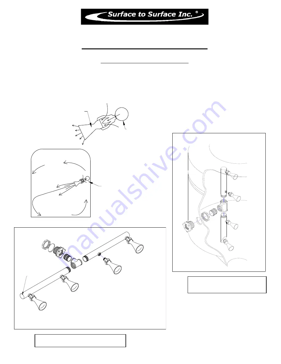
Internal Tank Jets - Installation
2" steel or PVC/ABS pipe
can also use for the manifold.
Cap or Seal Ends
Pipes can be rolled to stop dead spots and couplers can be welded onto 2" pipe at different angle
mount about 1/3 to 1/2 way up from the floor and aim toward the floor
and oppisite wall to creat a rolling effect
How they work.
Typical vertical installation in a
round cone bottom tank
Typical horizontal installation in a tank
For help with design and placement in
your tank, call Surface to Surface Inc.
and they will work with you to find the
best solution
ALL Jet Nozzles are mounted
on one side of the tank to
create a rolling effect in the tank.
Manifold
Jet Nozzles
For every gallon of fluid passing through the jet nozzle from the manifold pipe,
the jet nozzle will draw in another 4-5 gallon more from around the outside of
the nozzle, creating a larger volume of fluid movement in the tank.
Connect the manifold to the outlet on the filter/shear of the STS Mixing Unit.
Each unit is shipped with 2-4 jet nozzles that have been properly sized for the unit.
Summary of Contents for M2-H
Page 2: ...2 This page left blank intentionally ...
Page 13: ...13 ...
Page 18: ...18 M2 H Identifying Your Machine Components Location of Tags and PIN Plates ...
Page 19: ...19 SECTION II Description Care and Maintenance ...
Page 31: ...31 SECTION III Set up and Installation of Unit in Detail ...
Page 33: ...33 SECTION IV Operating the M2 Unit ...
Page 41: ...41 SECTION V Troubleshooting the M2 Unit ...
Page 44: ...44 SECTION VI Periodic Maintenance Repair Information ...
Page 49: ...49 SECTION VII OEM Repair Information ...
Page 62: ...62 ...
Page 63: ...63 ...
Page 64: ...64 ...
Page 68: ...68 SECTION VIII Parts Manual ...


