background image


54


TROUBLESHOOTING 


Review all SAFETY information in Section A. 


Before attempting to open or service the pump: 


1.  Familiarize yourself with this manual. 


2.  Lock out or disconnect the power source to 

ensure that the pump will remain 
inoperative. 


3.  Allow the pump to completely cool if overheated. 


4.  Check the temperature before opening any covers, 

plates, or plugs. 


5.  Close the suction and discharge valves. 


6.  Vent the pump slowly and cautiously. 


7.  Drain the pump. 


Summary of Contents for M2-H

Page 1: ...ALS ENCLOSED Unit Serial No _______________ Hydraulic Motor SNM2 11C106 Gorman Rupp Pump STS GR82E2 Serial No ________________ Control Valve Serial No __________________ Links relating to this Manual www stsmixers com www grpumps com STS 102 Rev 08 24 18 www stsmixers com Dealer ...

Page 2: ...2 This page left blank intentionally ...

Page 3: ... H 15 M2 H Foot Print top view 16 M2 H General Data Sheet 17 Identifying Your Machine Components 18 SECTION II Description Care and Maintenance Hydraulic powered centrifugal pump 20 23 Filter shear system 24 25 Venturi mixing tee 26 Wash wand 27 Dry hopper hopper valve 28 Internal tank jets 29 30 SECTION III Set up and installation of unit in Detail Permanent mounting of unit 32 Portable use of un...

Page 4: ... Typical transfer off loading operation 37 Shutdown cleanup storage Warm weather 38 Cold freezing weather 39 Prolonged periods of storage 40 SECTION V Trouble shooting Trouble Shooting the M2 42 43 SECTION VI Periodic Maintenance Repair Information Maintenance Schedule 45 Centrifugal Trash Pump Seal Replacement 46 Bolt torque Specifications 47 Notes 48 ...

Page 5: ...ONTENTS PAGE SECTION VII OEM Repair Information GR Centrifugal Pump Owner s Manual condensed 50 61 Gruvloc Pipe Couplings 62 64 Sauer Danfoss Hydraulic motor 65 67 SECTION VIII Parts Manual M2 H PARTS MANUAL 69 71 ...

Page 6: ...intenance including without limitation failure to inspect and maintain improper repair use of unapproved parts cracked engine heads and blocks unless caused by the failure of an internally lubricated part or repair of engine valves rings or guides 2 The Company s warranty does not apply to purchased components manufactured by others where separate warranty is made by the manufacture of such compon...

Page 7: ...ain to the engine motor and should also be followed This safety alert symbol appears with most safety statements It means attention become alert your safety is involved Please read and abide by the message that follows the safety alert symbol DANGER WARNING CAUTION CAUTION Caution without the safety alert symbol indicates an potentially hazardous situtation that can cause damage to the machine per...

Page 8: ...t WARNING Serious personal injury will result DO NOT REMOVE OR MODIFY SA FETY COVERS OR GUA RDS WARNING while the unit is in operation Serious personal injury will result NEVER ATTEMPT TO REMOVE OR CLEA N THE FILTER SHEA R CAUTION DO NOT POSITION ANY PARTOF YOURBODY over the hopper valve or mixingtee while cleaning rotate the flow control valve lev er tothe ST OP position tohalt the pump and fluid...

Page 9: ...EASE SEAL will result inleakage andpossible damage to the seal All maintenance operating andrepair of this unit must be done per the instructions inthe operators manual for safetyandreliability CAUTION WHENT RANSFERRINGFLUID tothe drill rig fluidpressure may reachor exceed50 p s i CHECKthe drill rigmanufacturers specifications regardingmaximuminlet pressures allowedfor their pump BEFORE ST ART ING...

Page 10: ...tive uses for this piece of equipment T his unit was designedfor the mixing and shearingof a dryadditive intoa liquidstream Other uses maycreate unforeseensafety issues andpersonal injuryrisk CAUTION LIFTINGLUGS OR T HE LIFT ING POINT S identified andlabelledonthe skid structure must be used inorder to safelylift andtransport the unit WARNING REFERTOTHESA FETY STATEMENTSIN THE OEM SUPPLIED MANUALS...

Page 11: ... ensure safe use of the equipment These include but are not limited to a Lifting points b Personal Protection recommendations c High temperature areas d Equipment dangers e Personal dangers f Fluid flow direction g Operating instructions SOME EXAMPLES FOUND ON THE EQUIPMENT Lifting Point Personal Protection Read and understand Operator s manual and Maintenance manual Hot Surface Fluid Flow Directi...

Page 12: ...rise above your set rate of 10 10 3 g p m of hydraulic flow The hydraulic flow valve should then be set back to the recommended flow rate of 10 10 3 g p m Specifications on hydraulic oil operating temperature and filtration can be found further on in this manual on the Sauer Danfoss hydraulic motor data sheets Any problems or question may be answered by calling Surface to Surface at 800 567 0978 d...

Page 13: ...13 ...

Page 14: ...RETURN out to Tank This line should discharge above the maximun fill line of the tank The air space will stop the siphon action of the fluid 2 NPT FLUID OUTLETS to Drill Rig Tank Guns 1 1 2 NPT ALL HOSES SHOULD BE KEPT TO THE SHORTEST LENGHT POSSIBLE TO ACHIEVE MAXIMUN PREFORMANCE Hose Hook ups Surface to Surface Inc M2 Series ...

Page 15: ...the desired consistency The operator can then transfer the final product to a second holding reservoir or directly to the drilling equipment The M2 H mixing unit consists of a hydraulic powered centrifugal pump filter shear unit venturi mixing tee assembly dry hopper pressure wash wand and a set of tank internal jets These components are all mounted together on a framed skid built for portability ...

Page 16: ...16 33 38 REV DATE DWR NUM Surface to Surface Inc CF EF IN 26 1 2 M2 H Hydraulic M2 H 011 17 11 Dry Weight 275 Lbs 125 Kg ...

Page 17: ...y StS Mixing System Fast efficient with high shearing ability Flow Valves Brass and Steel construction Withstand the abuse of daily operations Skid Frame Steel tube with lifting bale Built tough for the construction trade Hydraulic gear motor Requires 10gpm 1800psi Use your own power source no fumes in truck body Hydraulic Valve Hydraulic system Pump Variable speed controller Open loop circuit 2 C...

Page 18: ...18 M2 H Identifying Your Machine Components Location of Tags and PIN Plates ...

Page 19: ...19 SECTION II Description Care and Maintenance ...

Page 20: ...om around the plug threads This indicates that the pump housing is full and the plug can be tightened back up If no fluid is escaping from around the threads completely remove the plug carefully remove the plug Drill fluid or water can be poured into this opening to fill the pump cavity and a visual of the fluid level inside the pump can be made The level should be approximately to the top of the ...

Page 21: ...izing CAUTION BEFORE STARTING OR RESTARTING the engine and centrifugal pump make sure any valves installed on the pump suction inlet line are open and the fluid level in the tank is above the suction line CAUTION TRAPPED FLUID MAY BE PRESENT and will spill out when piping hoses pump or filter shear are removed Fig 4 WARNING REFER TOTHESAFETY STATEMENTSIN THE OEM S UPPLIED MA NUALS AND THISMANUAL R...

Page 22: ...ithium base grease until grease escapes from the relief hole Turn the grease cup arm counterclockwise until it is at the top of the stem this will release the spring to apply grease to the seal NOTE Some smoking and leakage may occur after installing a new seal assembly This should stop after the pump has run a while and the lapped seal faces have seated in Fig 5 ...

Page 23: ...nd build up inside of the cup and not allow the plunge to push to the full stroke This in turn will stop the supply of grease to the seal causing premature seal failure As a precaution it is strongly recommended that every 30 days the grease cup or the top of the grease cup be remove and the inside of the cup and the plunger be cleaned of all old grease Reassemble the plunger into the cup and chec...

Page 24: ...lter shear from the housing After the internal filter shear has been removed you will see on the end of the filter shear a pipe plug Fig 6b Remove the pipe plug and wash out the filter shear with clear water Reinstall the pipe plug into the filter shear reinstall the filter shear in the housing Do not clamp the 3 inch coupler until the 2 inch coupler and gasket are properly lined up After all piec...

Page 25: ...ntrol the flow and pressure of the discharge It is up to the customer to decide the piping arrangement and how they would use the discharge options The discharge flow can have high pressure and high volume flows associated with it and should be treated as such If you are unsure of the installation and routing of this flow contact Surface to Surface Inc for more details Also on top of the housing i...

Page 26: ...oduct inside of the mixing tee around the nozzle If this accumulation is left unattended over time it will build to the point of restricting the inlet of the mixing chamber This situation is easily rendered by using the wash wand to flush out the accumulation and force it back into the fluid stream Fig 8a Fig 8b CAUTION AVOID ALLOWING FOREIGN MATERIAL into the Venturi Mixing Tee thru the Hopper by...

Page 27: ...ple of this Fig 9b is to check the viscosity of the fluid using a marsh funnel Simply slow the engine speed down to reduce flow and pressure and put the wash wand inside the hopper with the hopper valve open and open the small valve located on the wash wand Rotate the valve handle to the on position and let it flow for approx 15 seconds close the valve and place the wash wand in the screening area...

Page 28: ...hecked regularly and kept tight to prevent movement The hopper valve must be kept free of dried Bentonite ice or other buildups to reduce the chance of damage during opening and closing The valve operates more smoothly if the surfaces are kept damp or wet All valves are to be opened and closed by hand DO NOT FORCE THE VALVE OPEN OR CLOSED visually check the valve if a problem occurs CAUTION AVOID ...

Page 29: ...r pulling fluid from the tank and into the external piping The internal tank jets requires little or no maintenance and will only require attention if they become clogged Flushing the entire system daily with clear water should eliminate any problems with this piece of the system The fluid passing through the internal tank jets is at a very high pressure and extreme caution should be used when vie...

Page 30: ...stallation in a tank For help with design and placement in your tank call Surface to Surface Inc and they will work with you to find the best solution ALL Jet Nozzles are mounted on one side of the tank to create a rolling effect in the tank Manifold Jet Nozzles For every gallon of fluid passing through the jet nozzle from the manifold pipe the jet nozzle will draw in another 4 5 gallon more from ...

Page 31: ...31 SECTION III Set up and Installation of Unit in Detail ...

Page 32: ... space or an opening will also have to be considered when mounting for the removal of the filter shear cartridge for regular cleaning and inspection Portable use of the unit If the M2 H is to be used as a portable unit there is a lifting bale Fig 12 connected to the sub frame to support and balance the unit when lifting or moving Properly approved and rated lifting apparatus should be used at all ...

Page 33: ...33 SECTION IV Operating the M2 Unit ...

Page 34: ...o assure the hydraulic oil reservoir has the proper fluid level for operating CHECK to assure the hydraulic filtering system is operating properly CHECK to assure the hydraulic variable speed controller is in the stop position CHECK to ensure the grease cup on the pump is full of grease and the winged lugged nut on the top is backed off to allow the shaft to retract into the grease cup CHECK to en...

Page 35: ...ber that the system is pumping fluid under pressure even when the valve is at a low setting Gradually rotate the control lever right toward the high speed position and set at the required speed GPM DO NOT EXCEED 10 3 GPM Use flow meter to determine GPM Note Whenever high speed operation is not required rotate the speed control lever left to approximately 1 2 speed to extend hydraulic motor and pum...

Page 36: ...sh wand Close the butterfly valve on the hopper to keep debris out of the system Allow the mixing system to circulate the product until the desired consistency is attained A sample of the mixed fluid may be taken at from the wash wand as described earlier in this manual on the wash wand description page Note Whenever high speed operation is not required rotate the speed control lever left to appro...

Page 37: ...stop the flow normally mounted on the drill rig The tank jet valve will need to be in the open position to act as a relief when the valve on the drill rig is closed If transferring to a reservoir tank the outlet valve on the filter shear housing is used to start stop the flow of fluid When removing the mixed fluid from the tank to the drill rig or reservoir leave an amount of fluid in the bottom o...

Page 38: ...nk with clear water and then start the motor and pump By pumping this water through the entire system it will remove buildup and dilute any remaining mixed fluid in the system Open the valve on the wash wand and flush it back into the hopper Open the hopper valve to drain then close Move the control lever to the most left position against the stop pin to stop the motor and pump STOP the hydraulic ...

Page 39: ...rain Remove centrifugal pump front drain plug Leave the pump plug out Make sure both Outlet valves and wash wand valve are open Remove filter shear and clean as described in the maintenance section of this manual Leave filter shear out of housing as this will allow remaining moisture to drain Open the hopper valve and pour in a suitable environmentally friendly anti freeze until it runs out of the...

Page 40: ...xtend the life of your unit Prolonged periods of storage require extra care of the pump to protect from rusting internally Separate the pump as you would to replace the seal to dry and spray with a protective oil film Prolonged periods of storage require other preparation See engine OEM manuals WARNING REFER TO THE SAFETY STATE MENTS IN THE OEM SUPPLIED MANUALS AND THIS MANUAL REGARDING THESE OPE ...

Page 41: ...41 SECTION V Troubleshooting the M2 Unit ...

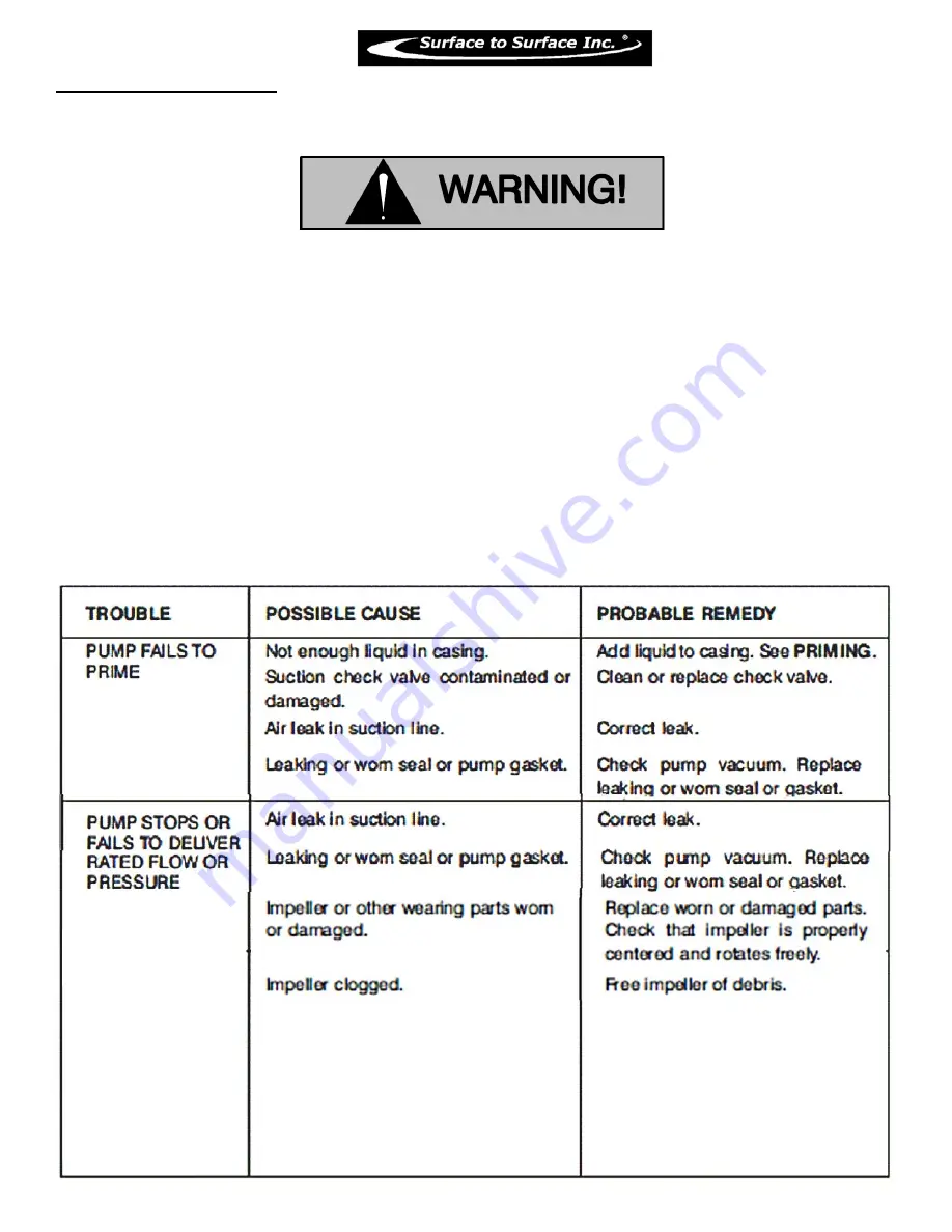
Page 42: ...oubleshooting is as follows Everything before the pump is being sucked has vacuum Everything after the pump is being blown has pressure The following may aid in any problems that may arise No fluid flow low fluid flow Pump not primed Prime pump Suction valve is closed Open suction valve Suction valve is broken and not opening inside properly Replace valve Plugged suction inlet inside of the tank C...

Page 43: ... at the end of the discharge hose is closed or damaged Open or replace valve No fluid flow low fluid flow See above solutions Wash wand has little or no flow or pressure Wash wand valve is closed or damaged Open wash wand valve or replace Wash wand nozzle hole in the end is plugged Shut off unit and clean out wash wand hole No fluid flow low fluid flow See above solutions Fluid does not seem to mi...

Page 44: ...44 SECTION VI Periodic Maintenance Repair Information ...

Page 45: ...al check of variable speed controller 0 Visual inspection of inline flow meter 0 Pump Components Check General Condition Visual Temperature Unusual Noise or Vibrations Cracks Leaks Loose hardware 0 Check Fill grease cup for mechanical seal 0 Check pump mechanical seal for leakage dripping 0 Clean old grease build up from inside of Grease Cup 0 Check front impeller clearance wear plate 0 Check rear...

Page 46: ...the shaft shoulder Determine the correct position for the rotating element and slide it onto the shaft Sub assemble the inboard stationary element packing ring and spring washer and press this subassembly into the lubricated seal liner A push tube cut from a length of plastic will aid seal installation The O D of the tube should be about the same size as the O D of the seal spring Install the spac...

Page 47: ...0 550 400 7 8 490 360 625 450 700 500 875 650 1 725 540 925 675 1050 750 1300 975 Lubricated means coated with a lubricant such as engine oil or fasteners with phosphate and oil coatings Dry means plain or zinc plated without any lubrication Metric size Thread size x pitch mm N m ft lbs M6 X 1 0 10 8 1 0 8 0 0 5 M8 x 1 25 25 5 2 9 19 0 2 0 M10 x 1 5 49 0 4 9 36 0 4 0 M12 x 1 75 88 3 9 8 65 0 7 0 M...

Page 48: ..._____________________ __________________________________________ __________________________________________ __________________________________________ __________________________________________ __________________________________________ __________________________________________ __________________________________________ __________________________________________ __________________________________...

Page 49: ...49 SECTION VII OEM Repair Information ...

Page 50: ...llation Pumps and related equipment must be installed and operated according to all national local and industry standards If there are any questions regarding the pump or its application which are not covered in this manual or in other literature accompanying this unit please contact Surface to Surface or your STS distributor Surface to Surface Inc 1 800 567 0978 The following are used to alert ma...

Page 51: ...hich the pump driver and or controls have not been approved or which may damage the pump or endanger personnel as a result of pump failure Use lifting and moving equipment in good repair and with adequate capacity to prevent injuries to personnel or damage to equipment Suction and discharge hoses and piping must be removed from the pump before lifting Make certain that the unit and all piping or h...

Page 52: ...6 Refer to instructions in this manual before restarting the pump Do not remove plates covers gauges pipe plugs or fittings from an overheated pump Vapor pressure within the pump can cause parts being disengaged to be ejected with great force Allow the pump to completely cool before servicing Never run this pump backwards Be certain that rotation is correct before fully engaging the pump Pumps and...

Page 53: ...is liquid in the pump casing Never operate this pump unless there is liquid in the pump casing The pump will not prime when dry Extended operation of a dry pump will destroy the seal assembly Add liquid to the pump casing when 1 The pump is being put into service for the first time 2 The pump has not been used for a considerable length of time 3 The liquid in the pump casing has evaporated Once th...

Page 54: ...urself with this manual 2 Lock out or disconnect the power source to ensure that the pump will remain inoperative 3 Allow the pump to completely cool if overheated 4 Check the temperature before opening any covers plates or plugs 5 Close the suction and discharge valves 6 Vent the pump slowly and cautiously 7 Drain the pump ...

Page 55: ... gauge readings if so equipped between regularly scheduled inspections can indicate problems that can be corrected before system damage or catastrophic failure occurs The appearance of wearing parts should also be documented at each inspection for comparison as well Also if records indicate that a certain part such as the seal fails at approximately the same duty cycle the part can be checked and ...

Page 56: ...l Valve Weight Suction Flange L W 14 15 16 17 18 11 11 3 8 L W 4 3 2 3 4 5 6 7 8 9 2 10 11 12 13 14 15 16 17 2 18 STS PART NUMBER 076 33622 060 GR682215990 060 GRD0615991 060 GR427A10010 060 GR8314080 060 GR229G18000 060 GRGS1000 060 GR2X17090 060 GRC060615991 060 GRP1215079 060 GRB061415991 060 GRKF0618040 060 GRX040317090 060 GRJ0417090 060 GR19B10010 060 GR1361G19070 060 GR135415160 060 GR13611...

Page 57: ...rce representative Before attempting to open or service the pump 1 Familiarize yourself with this manual 2 Lock out or disconnect the power source to ensure that the pump will remain inoperative 3 Allow the pump to completely cool if overheated 4 Check the temperature before opening any covers plates or plugs 5 Close any suction and discharge valves 6 Vent the pump slowly and cautiously 7 Drain th...

Page 58: ... in the threaded grease piping hole and not damage the threads Debur the hole from the inside of the seal liner after drilling Seal Reassembly and Installation Figures 1 and 3 Clean the seal cavity and shaft with a cloth soaked in fresh cleaning solvent Most cleaning solvents are toxic and flammable Use them only in a well ventilated area free from excessive heat sparks and flame Read and follow a...

Page 59: ...ld be between 0 010 and 0 020 inch 0 25 to 0 51 mm Measure this clearance and add or remove shims from the impeller adjusting shim set until the correct clearance is achieved Pump Casing and Wear Plate Installation If the wear plate assembly 9 was removed install the new wear plate in the pump casing and secure it with the hardware 2 13 Install a new set of casing gaskets 5 and slide the pump casi...

Page 60: ...l the grease cup 1 through the grease fitting with No 2 lithium base grease until grease escapes from the relief hole Turn the grease cup arm counterclockwise until it is at the top of the stem this will release the spring to apply grease to the seal see Figure 4 NOTE Some smoking and leakage may occur after installing a new seal assembly This should stop after the pump has run a while and the lap...

Page 61: ... shaft shoulder Determine the correct position for the rotating element and slide it onto the shaft Sub assemble the inboard stationary element packing ring and spring washer and press this subassembly into the lubricated seal liner A push tube cut from a length of plastic will aid seal installation The O D of the tube should be about the same size as the O D of the seal spring Install the spacer ...

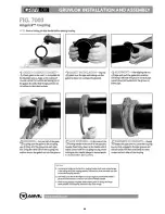
Page 62: ...62 ...

Page 63: ...63 ...

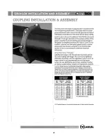
Page 64: ...64 ...

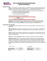
Page 65: ...etroleum mineral based fluids High temperature limits apply at the inlet port to the motor The motor should run at or below the maximum continuous temperature The peak temperature is based on material properties Don t exceed it Cold oil generally doesn t affect the durability of motor components It may affect the ability of oil to flow and transmit power For this reason keep the temperature at 16 ...

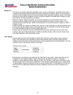
Page 66: ... Beta ratio βx For Discharge filtration with controlled reservoir ingression use a β35 45 75 filter Pressure filtration use a pressure filtration with an efficiency of β10 75 βx ratio is a measure of filter efficiency defined by ISO 4572 It is the ratio of the number of particles greater than a given diameter x in microns upstream of the filter to the number of these particles downstream of the fi...

Page 67: ...d level Put the return line below the lowest expected fluid level to allow discharge into the reservoir for maximum dwell and efficient deaeration A baffle or baffles between the return and suction lines promotes deaeration and reduces fluid surges Line sizing Choose pipe sizes that accommodate minimum fluid velocity to reduce system noise pressure drops and overheating This maximizes system life ...

Page 68: ...68 SECTION VIII Parts Manual ...

Page 69: ...423 00002 5 Wash Wand M2 619 1 2 Coupler EPDM Gasket 020 390 078640 2 Groove Loc Coupler 020 390 00026 3 B 21 22 23 1 End Pipe M2 607 5 2 B Pipe Clamp 1 1 2 Jetting Nozzel M2 608 1 2 Mixing Tee M2 609 2 Grooved Venturi M2 610 2 NPT Grooved Adaptor M2 611 1 24 25 26 27 28 29 2 Grooved Butterfly Valve 023 7005 011049 1 Foam Strip 084 1 8 WSTRIP 4 1 Hand Knob 084 135 039 2 Hopper M2 612 1 30 31 32 33...

Page 70: ...ORB x 3 8 JIC 90 Elbow 029 2503 6 6 Foot Spacer 15 1 B Hyd Flow Control Mount M2 704 29 P N PU M2 H 046 FCRS1 12SAE 029 0503 12 10 3 4 ORB x 5 8 JIC Male Adpt 1 3 4 ORB x 3 4 JIC 90 Elbow 029 2503 12 12 3 4 JIC Swivel Nut Run TEE 029 063T 12 12 12 3 4 ORB x 3 4 JIC Male Adpt 029 0503 12 12 Cap shipping purpose only 029 06CP 12 2 30 PAINT Black B 1 1 Max flow 3 8 Decal 2 Max flow 3 4 Decal Grease C...

Page 71: ... Casing 1 1 1 1 1 1 1 1 Stud 4 Pipe Plug Hex Cap Screw 1 1 Fiber Washer Large Valve Weight CheckValve Gasket Small Valve Weight Suction Flange L W 14 15 16 17 18 060 GR682215990 060 GRC060615991 060 GRP1215079 060 GRB061415991 060 GRKF0618040 060 GRX040317090 060 GRJ0417090 060 GR19B10010 060 GR1361G19070 060 GR135415160 060 GR136113040 1 Filler Pipe Plug 19 060 GR48271 063 060 GR46472 309 1 Impel...

Reviews: