- 14 -
Cont ...
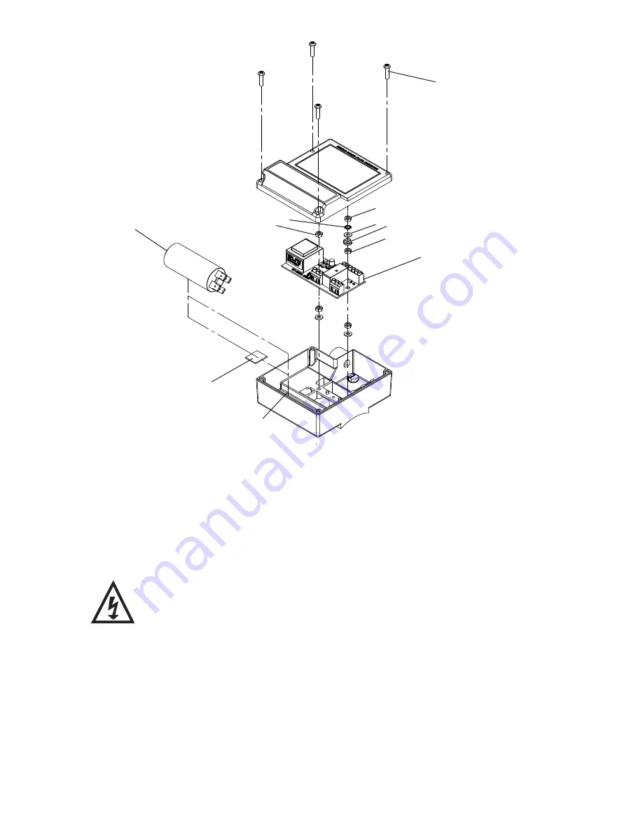
Reference Fig 25.
•
Remove four screws (Item 22) and carefully remove terminal box lid.
•
IMPORTANT
: Take note of capacitor wiring connection and colours
before removal
.
•
Disconnect and remove capacitor, and foam securing pad (Item 19) make note of pad fitted
position.
•
Remove M4 nut (Item A) then M4 lock washer (Item B) and plain washer (Item C), this
allows removal of earth wire and cup washer (Item D).
•
Disconnect all wiring from terminal blocks on printed circuit board (PCB Item 17).
•
Remove two M4 nuts (item A) and carefully lift PCB (Item 17) away from terminal box.
Damaged components must be replaced. Contact Stuart Turner for advice
on replacements not supplied with kit.
•
REASSEMBLY
Reassembly is the reverse of the disassembly instructions with the new replacement parts
fitted as required.
Note: For correct installation the capacitor must be secured and positioned as detailed in
Figs. 26 & 27.
Secure PCB nuts to a torque of 1.5 Nm (item A).
Secure terminal box lid screws to a torque of 0.8 Nm (item 22).
IMPORTANT NOTE
: For correct pump rotation, ensure both blue wires are connected to the
linked capacitor terminals as shown.
Fig. 25
D
Capacitor
22
19
A
C
B
A
Capacitor
17
A


