background image

Powering On the Welder 

When 

all of the previous setup steps 

in this manual are complete the welder can be powered on.


1. Ensure that the power cord is connected to the power cord socket and the supply power.
2. Check the 10A fuse below the ON/OFF switch located on the back of the unit.
3. Use the ON/OFF switch to power the unit on.

Voltage Selection


The voltage is determined by the diameter of the stud and the base material thickness. The unit is

programmed with the recommended voltage settings for various stud sizes. 

Fine tuning the volt-

age for each application from this starting point is recommended.

Setting the required weld voltage is achieved by selecting the desired stud size on the screen or

manually setting the voltage by using the 

+

 or 

-


arrows.

Fast voltage selection can be done from the voltage mode screen. This will replace the preset val-

ues on the screen with voltages in increments of 10V and can be manually adjusted by using the

arrows.

Testing the Weld Settings


1. After performing all of the setup steps listed in this manual, it is recommended that several test

welds be performed with the same diameter stud and base material used for the application. This

will verify that all of the settings are correct to achieve the desired results.

2. Welding is done by placing the stud into the collet and pressing the stud gun to the work piece.
3. Hold the gun perpendicular to the work piece, align the stud to the desired location, press down

so that the foot piece is flush with the base material, and squeeze the trigger.

4. Spreading the collet tines when lifting the stud gun from the welded stud will shorten the life of

the collet and will eventually create an undesirable weld. 

For maximum collet life remove the

stud gun from the welded stud by pulling the stud gun straight off of the welded stud.

5. Properly welded studs are tested by either torqueing or bending the stud. Using either method

the threaded portion of the stud may break. However, the welded flange of the stud should stay

in place. Additionally, if the base material is very thin, a full slug the diameter of the flange will

pull from the base metal.
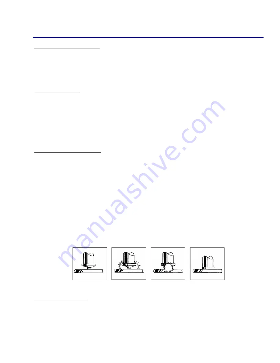
Inspecting the Weld


1. Visually inspect the weld. If there is a significant amount of splatter then the weld is too hot, lower

the voltage. If there is no splatter then the weld is too cold, increase the voltage.

2. A good weld will result in a small, visible, and 360° flashing surrounding the flange of the stud. If

there is weld flash on only one side of the base of the flange, this is called “arc blow,” and can be

solved by repositioning the ground clamp or using a dual ground clamp.

SETUP AND WELDING 

11


WWW.STUDWELDPROD.COM 

800-252-1919

Summary of Contents for StudPro 2500XI

Page 1: ...OPERATOR S MANUAL STUDPRO SERIES Capacitor Discharge Stud Welder MODELS StudPro 2500XI StudPro 2500XIP StudPro 3125XI StudPro 3750XI WWW STUDWELDPROD COM 800 252 1919...

Page 2: ...Description Pages Warranty Information 1 Safety 2 Specifications and Features 3 Product Components 4 5 Screen Operation 6 8 Setup and Welding 9 11 CD Stud Gun Exploded View 12 WWW STUDWELDPROD COM 800...

Page 3: ...hearing Wear earplugs or oth er protective gear if applicable Fumes and gases expelled during welding can be health hazards Make sure welding is done in a well ventilated area Hot metal splatter can c...

Page 4: ...ating or poor input power Rigid internal construction minimizes the possibility of components coming loose during rough han dling or operation Hand tool has been ergonomically designed to reduce opera...

Page 5: ...P only on all other TW i models this connector is a secondary Weld Ground Connector 4 Stud Gun Control Cable Connector 5 Stud Gun Weld Cable Connector 6 ON OFF Switch 7 10A Fuse 8 Manufacturer Model N...

Page 6: ...tion Fan 2 ON OFF Switch 3 10A Fuse 4 AC Inline Filter Power Cord Socket 5 Capacitor Bank 6 Freewheeling Diodes 7 SCR Clamp 8 Discharge Resistor 9 Control Board PRODUCT COMPONENTS 4 3 1 2 5 9 8 7 6 5...

Page 7: ...ts Metric Stud Mode Contact Indicator Stud Preset Screen Voltage Preset Screen Charge Indicator Welding Voltage Stud Counter Voltage Adjustment Adjustment Voltage Presets Mode Selection Voltage Mode S...

Page 8: ...RESET tab located at the bottom of the screen The screen will then prompt the user for a confirmation to clear the stud counter To cancel the resetting of the stud counter simply press NO on the scre...

Page 9: ...e Limiter Activated Protects capacitor from overheating by limiting the user to a maximum average duty cycle This protec tion only activates when the set point of the welder is above 85V Below 85V the...

Page 10: ...t on the unit Push the plug firmly into the socket and twist clockwise to secure the plug into the correct position 3 Connect the ground clamp into the ground terminal socket on the front of the unit...

Page 11: ...ount the two legs and foot piece onto the stud gun The collet should be centered through the opening of the foot piece 3 Insert the stud to be welded into the collet 4 Adjust the leg and foot piece by...

Page 12: ...chieve the desired results 2 Welding is done by placing the stud into the collet and pressing the stud gun to the work piece 3 Hold the gun perpendicular to the work piece align the stud to the desire...

Page 13: ...CD GUN EXPLODED VIEW 12 WWW STUDWELDPROD COM 800 252 1919...

Page 14: ...8 CDB 037 10 MM CDB 010M SOYER COLLETS STUD DIA PART NO 6 CDBS 013 4 MM CDBS 004M 8 CDBS 015 10 CDBS 018 5 MM CDBS 005M 6 MM CDBS 006M 1 4 CDBS 025 5 16 CDBS 031 CAPACITOR DISCHARGE ACCESSORIES 3 8 D...

Page 15: ...TUD STOP LENGTH LENGTH PART NO 1 4 1 1 4 033 781 3 8 1 1 8 033 782 1 2 1 033 783 5 8 7 8 033 784 3 4 3 4 033 785 7 8 5 8 033 775 1 1 2 033 776 1 1 8 3 8 033 777 1 1 4 1 4 033 778 1 3 8 BUTTON STOP 1 8...

Page 16: ...015 100 10 X 1 4 CI 018 025 10 X 3 8 CI 018 037 10 X 1 2 CI 018 050 10 X 5 8 CI 018 062 10 X 3 4 CI 018 075 10X 1 CI 018 100 1 4 X 1 4 CI 025 025 1 4 X 3 8 CI 025 037 1 4 X 1 2 CI 025 050 1 4 X 5 8 CI...

Page 17: ...WWW STUDWELDPROD COM 800 252 1919 WWW STUDWELDPROD COM 800 252 1919...

Reviews: