background image

A730 CD Player

16.11.00 BN

Upgrade Kit 1.630.027.81

Page 2 of 7

Bracket on front panel

CD drive


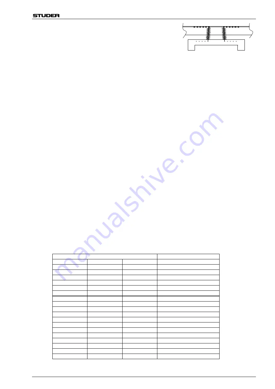
Fit the two tension springs put aside before according to the figure;
the spring mounting holes are partially covered by the CD drive
frame.

Position of the CD drive


The exact position of the CD drive is important. For adjustment, the front panel must be placed to the bottom
of the player. Check with an inserted CD if the air gap is of equal width around the circumference of the disk.
If so, tighten the four screws linking the CD drive frame with the front panel.

Servo Board Modification


Remove the insulating sheet and all remainders of the adhesive foam tape from the solder side of the board
(1.630.051.85/86). Put the insulating sheet aside for later use.


Perform the following modifications on the Board (1.630.051.85/86): R48 (22 k

), replace by 10 k

(57.11.3103); R16 (270 k

), replace by 130 k

 (57.11.3134); R17 (51 k

), replace by 22 k

 (57.11.3223);

C21 (68 pF) , replace by 330 nF (59.06.0334) in series with 56 k

 (57.11.3563).


Remove the following parts: TP17, TP18, TP24, TP28, J1, J3, J7, C66, R73 (trimmer pot), and IC6.


The 100 nF capacitor (59.03.2104) is connected to TP19 (HF-RET); its second terminal is soldered to the
solder lug (29.26.1002), refer to fig. 1. Test points TP2 and TP3 must be bent by 90°, refer to fig.1; we ur-
gently recommend to unsolder them before bending.


Solder the pre-fabricated wires (1.630. 114.93) to the corresponding solder pads according to the table be-
low and to fig. 1 (at the former positions of connectors J1 and J3). Tie the cables with the wire straps
(35.03.0109) according to fig. 4 and 5. Solder the two twisted wires (brn, blk) to the corresponding pads on
the PCB (refer to the table below and to fig. 1).


Solder the small Driver Brush Motor PCB (1.630.075.00) at the location of IC6. The ZIP connector for the flex
PCB and its wires will be located between the Driver Brush Motor PCB and the Servo Board, therefore
please leave sufficient space between the two PCBs. For details please refer to fig. 1 and 4.


Caution: 

The clearance between the CD drive and the Servo Board is extremely narrow; therefore the com-

ponent leads on the solder side marked grey in fig. 3 must be cut very short.


Cut a rectangular insulating sheet (dimensions: 122 x 100 mm) out of the insulating sheet put aside before;
refer to fig. 1. Fix this insulating sheet as shown in fig. 3 to the solder side of the Servo Board, using five
pieces of the double-sided adhesive foam tape contained in the kit. The foam tape has to be positioned ac-
cording to fig. 1 and 3; press the insulating sheet firmly to the foam tape.


Drill two holes 

 3.2 mm into the insulating sheet such that they match the two mounting holes of the PCB.


Fold the flat ribbon cable as shown in fig. 1. Stick the label “1.630.072.00” over the label “1.630.051.86” and
solder the two twisted wires to the motor’s soldering tags (brn wire to red dot).


Reinstall the Servo Board, using the four 2 mm spacers (1.010.165.27) between mounting frame and Servo
Board. Fix the Servo Board with the three M3×8 screws (21.53.0355), and the countersunk screw M3
(21.99.0121) next to the Driver Brush Motor PCB.


Connect the Flex PCB to the ZIP connector. After having locked the connector (shift the locking clip towards
the wire end of the connector), it must be fixed to the Servo Board using a piece of double-sided adhesive
foam tape. Position the connector exactly as indicated in fig. 4 – 

the flex PCB of the CD drive as well as the

two wires to the motor must be free in all directions – it must by no means be under tensile stress.


If using the additional Service Kit 1.630.060.00, replace the 3-pin housing of the lock solenoid connector
(plugged to socket J4) by the 5-pin housing contained in the kit, refer to fig. 7.

Source

Destination

J1, pin no.

Signal name

Wire color

Conn. CDM-4 (ZIF), pin no.

1

GND

brn

14

2

D1

red

10

3

D2

org

9

4

D3

yel

11

5

D4

grn

12

6

S

blu

13

7

G

vio

8

8

FOC-

gry

1

9

FOC+

wht

2

10

LO

blk

6

11

LM

red

7

12

LG

org

5

J3, pin no.

Signal name

Wire color

1

RAD+

brn

3

2

RAD-

red

4

TP

Signal name

Wire color

DC-Motor, pin

24

+5V

brn

red

 dot

28

VM

blk

no mark

Summary of Contents for 1.630.027.81

Page 1: ...nutzt werden Servo Board 1 630 051 86 ist in diesem Kit ebenfalls enthalten Vorbereitung und Modifikation Trennen Sie das Gerät vom Netz Öffnen Sie das Gerät durch vorsichtiges Entfernen der Frontabdeckung Bedienungsteil Lösen Sie dazu die sechs Innensechskant Schrauben Bewahren Sie diese Schrauben auf Diese sind von der Unterseite der Front zugänglich die ganze Frontplatte mit dem LW kann durch A...

Page 2: ...en kommen teilweise zwischen dem Driver Brush Motor PCB und dem Servo Board zu liegen lassen Sie deshalb genügend Abstand zwischen den beiden Platinen Details finden Sie in Fig 1 und 4 Vorsicht Der Raum zwischen LW und Servo Board ist sehr knapp Die in Fig 3 grau markierten Lötan schlüsse auf der Lötseite des Boards müssen ganz kurz geschnitten werden Schneiden Sie eine rechteckige Schutzfolie gem...

Page 3: ...nd Position der Schutzfolie Ansicht auf Bestückungsseite Figur 1 Servo Board 1 630 051 86 heisst nach dem Umbau 1 630 072 00 FOCUS OFFSET LASER RAD OFFSET VERANY Track 38 min dropouts 50 mV 2 mV Details see fig 7 0 V 5 mV zum Motor Schutzfolie Lötseite 1 630 072 00 100 mm 122 mm 114 mm 2 x Ø 3 2 mm 4 mm Pin 1 ...

Page 4: ...d auf dem Servo Board fixiert Fig 7 Das Servo Board 1 630 051 85 86 besitzt für die Verbindung zum Ver riegelungsmagneten neu eine 5 polige Buchse 3 polig bei der früheren Versi on 1 630 051 00 Das Steckergehäuse muss gemäss Figur durch das 5 polige Steckergehäuse ersetzt werden im Kit 1 630 060 00 enthalten Nach leichtem Druck auf die Verriegelungsfahne können die Steckkontakte aus dem 3 poligen ...

Page 5: ...onkleber auf dem Print fixiert und festgelötet werden kann Das Servo Board wird J3 berühren J3 muss daher um 180 gedreht werden der Verpolungsschutz Draht muss von Pin6 J3 auf Pin 3 J3 umgesteckt werden Vorsicht Vor dem Einlöten von J3 muss ein Rest der zerschnittenen Isolationsfolie oder allenfalls ein geeignetes Stück Papier zur Isolation zwischen J3 und den Print gelegt werden Kurzschlussgefahr...

Page 6: ...A730 CD Player 16 11 00 BN Upgrade Kit 1 630 027 81 Page 6 of 7 Geändertes Schema Servo Board 130k 22k 330n 56k 5V Disc DC Motor IC6 1 630 075 XX 10k brown wire black wire ...

Page 7: ...d erscheinen in der Anzeige zwei Balken Focus Offset Stellen Sie während dem Abspielen der CD zwischen TP7 und TP25 mit R33 eine Spannung von 0 5 mV ein Hinweis Die Dicke der eingelegten Disk nominale Dicke 1 23 mm hat einen entschei denden Einfluss auf die Einstellung des Focus Offset Die Test CD Philips SBC444 entspricht dieser Spe zifikation Radial Offset Legen Sie die Test CD Vérany Digital Te...

Page 8: ...86 is contained in this kit too Preparation Modification Unplug the unit from the mains Open the unit by carefully removing the front operating panel by means of unscrewing the six Allen screws accessible from the bottom side The complete front panel with the drive can then be flipped over to the left and placed onto your workbench next to the bottom part of the CD player Now you see the Servo Boa...

Page 9: ...ent space between the two PCBs For details please refer to fig 1 and 4 Caution The clearance between the CD drive and the Servo Board is extremely narrow therefore the com ponent leads on the solder side marked grey in fig 3 must be cut very short Cut a rectangular insulating sheet dimensions 122 x 100 mm out of the insulating sheet put aside before refer to fig 1 Fix this insulating sheet as show...

Page 10: ...lating Sheet Position Component Side View Fig 1 Servo Board assy no changed from 1 630 051 86 to 1 630 072 00 after modification FOCUS OFFSET LASER RAD OFFSET VERANY Track 38 min dropouts 50 mV 2 mV Details see fig 7 0 V 5 mV To motor Insulating sheet on solder side 1 630 072 00 100 mm 122 mm 114 mm 2 x Ø 3 2 mm 4 mm Pin 1 ...

Page 11: ...2 holes fixed on solder side with 5 pcs of self adhesive foam tape Fig 7 On the Servo Board 1 630 051 85 86 a 5 pin connector is used for the connec tion to the lock solenoid the former version 1 630 051 00 had a 3 pin connector Remove the two pin contacts from the former connector housing by carefully pressing down the detent spring with a pointed tool while pulling Slightly bend the detent sprin...

Page 12: ...y fix it to the PCB with hot melt or silicone adhesive and solder its leads to the corresponding pads The Servo Board will be touching J3 Therefore J3 must be rotated by 180 Unsolder J3 move the key wire from pin6 to pin3 Caution Before inserting and soldering J3 in its new position put an appropriate cutting of the insulating sheet or possibly a piece of solid paper between J3 and the PCB as an i...

Page 13: ...A730 CD Player 16 11 00 BN Upgrade Kit 1 630 027 81 Page 6 of 7 Modified Servo Board Diagram 130k 22k 330n 56k 5V Disc DC Motor IC6 1 630 075 XX 10k brown wire black wire ...

Page 14: ...the voltage between TP7 and TP25 to 0 5 mV with R33 Tip The thickness of the inserted disc has a crucial influence on the focus offset adjustment and refers to a nominal disc thickness of 1 23 mm The Philips SBC444 test disc fulfills this specification Radial Offset Insert the Vérany Digital Test 2 test CD order no see table below Play track 38 and ad just with R77 the reproduced sine wave to mini...

Reviews: