19
I
GB
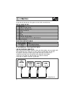
OPERATING
BASIC STATE OF BATTERY CHARGER
FEMALE CONNECTOR (DB 9)
Description
CAN BUS terminator (124 ohm)
CANL signal - CAN BUS interface
Battery charger negative
Not used
Earth
Not used
CANH signal - CAN BUS interface
Basic state of the battery charger (+V output, 20mA max)
+5Vdc (10 mA max)
PIN 8 connection
HIGH IMPEDENCE
+V OUTPUT
State
OFF OR PROBLEMS PRESENT
ON OR NO PROBLEMS PRESENT
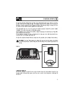
For a wiring example of control signals look at figure 3b.
CAN BUS NETWORK CONNECTION
When making the data interface connection (CANH and CANL signals) use an unscreened cable
with a twisted pair (cross-section 0.25/ 0.35 mm
2
AWG 22/24, impedance 100/150 ohm).
The maximum total length of the data signal cable should be no more than 100 m.
Activate the terminator at the first and last device connected to the network.
If there is only one device, the terminator does not need to be activated.
An example of a network connection is given below:
PIN
1
2
3
4
5
6
7
8
9
The position and description of the signals on the connector are listed below:
CAN-H(7)
CAN-L(2)
TERM(1)
CAN-H
CAN-L
TERM
CAN-H
CAN-L
TERM
CAN-H
CAN-L
TERM
*
Optional devices.
*
*
*
TEMPERATUR
BATTERIES
SENSOR
MBC
BATTERY
CHARGER
CURRENT
SENSOR
LCD
TERMINAL
Summary of Contents for Innotec MBC 12-25/3
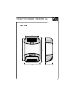
Page 13: ...205 181 90 135 155 75 MBC BATTERY CHARGER DIMENSIONS mm 12 08 2 12 12 2 11 ...
Page 14: ...12 268 244 90 135 155 75 MBC BATTERY CHARGER DIMENSIONS mm 12 25 3 24 12 2 ...
Page 29: ...280 334 272 220 127 MBC BATTERY CHARGER DIMENSIONS mm 12 30 3 12 40 3 27 ...
Page 30: ...28 358 412 272 220 127 MBC BATTERY CHARGER DIMENSIONS mm 12 60 3 24 30 3 ...
Page 45: ...447 495 272 220 127 12 80 3 24 60 3 24 80 3 43 MBC BATTERY CHARGER DIMENSIONS mm ...


